

Can we renovate a granite ruin almost from scratch?
Started 2y. Edited 3moStarted about 2 years ago. Last edit 4 months ago
Construction
In Progress
Building
More Information


%20--%3e%3csvg%20version='1.1'%20id='Layer_1'%20xmlns='http://www.w3.org/2000/svg'%20xmlns:xlink='http://www.w3.org/1999/xlink'%20x='0px'%20y='0px'%20viewBox='0%200%2064%2063'%20style='enable-background:new%200%200%2064%2063;'%20xml:space='preserve'%3e%3cstyle%20type='text/css'%3e%20.st0{fill:%23231F20;}%20%3c/style%3e%3cdesc%3eCreated%20with%20Sketch.%3c/desc%3e%3cg%20id='Page-1'%3e%3cg%20id='OA-Logo-Black-Background'%3e%3cpath%20id='Shape'%20class='st0'%20d='M14.1,30.1c-1.5-0.8-8.6-3.8-14.1-7.8c1.8-3.4,3.1-5.6,5-9.1c2.7,1.1,1.9,0.5,4.6,1.7%20c0.8,0.4,10.1,4.5,13.8,6.2c2.4,1.1,4.7,2.2,7,3.3L43,30.5l8.1,3.9c4,2,7.2,3.5,11.3,5.5c0.5,0.3-3.7,9.4-3.7,9.4%20c-1.7-0.6-3.9-1.8-5.5-2.5c-4.7-2.1-9-3.9-13.7-6c-4-1.8-6.7-2.9-10.8-4.5C25,34.9,17.1,31.6,14.1,30.1z'/%3e%3cpath%20id='Shape_1_'%20class='st0'%20d='M12.1,54.9c-0.8,0.6-1.6,1.2-2.5,1.6c-0.4-0.5-0.9-1-1.3-1.5c-0.3-1.2-2.3-4.9-2.7-6.2%20c-0.1-0.4-0.7-2.2-0.8-2.6c0,0,5-3.4,8.2-5.9c3.2-2.6,6.2-5,9.3-7.5c1.4-1.1,3.9-2.5,5.3-3.5c2.5-1.7,13-9.1,15.6-10.5%20c5.4-3.3,11.1-6.3,16.8-9c1.7,3.5,1.8,3,3.8,6.9c0,0-17.8,13.5-22.7,17.1c-3.8,2.8-7.5,5.7-11.3,8.5c-1.7,1.3-3.5,2.4-5.2,3.7'/%3e%3cpath%20id='Shape_2_'%20class='st0'%20d='M20.8,2.9l-0.2-0.8C25,0,31.2-0.3,31.4,0.2c0.4,1.1,0.9,2.2,1.2,3.4c1.4,4.4,2.7,8.7,4,13.1%20c0.4,1.4,2.8,10,2.9,10.5c0.5,2.8,1.2,5.6,1.6,8.4c0.8,4.7,1.4,8.6,2.3,13.3c0.6,3.1,1.3,6.3,2.3,11.3c0,0-5.8,1.4-7.5,1.8%20c-0.8,0.2-1.5,0.4-2.4,0.6c-0.3-1.1-0.2-1.2-0.5-2.1c-0.9-3.7-1.8-7.3-2.6-11c-1.5-6.4-3-12.9-4.4-19.3%20c-1.2-5.4-2.6-10.7-4.4-15.9c-1-3.1-1.8-6.3-2.7-9.5C21.1,3.8,21,3.8,20.8,2.9z'/%3e%3c/g%3e%3c/g%3e%3c/svg%3e)


1
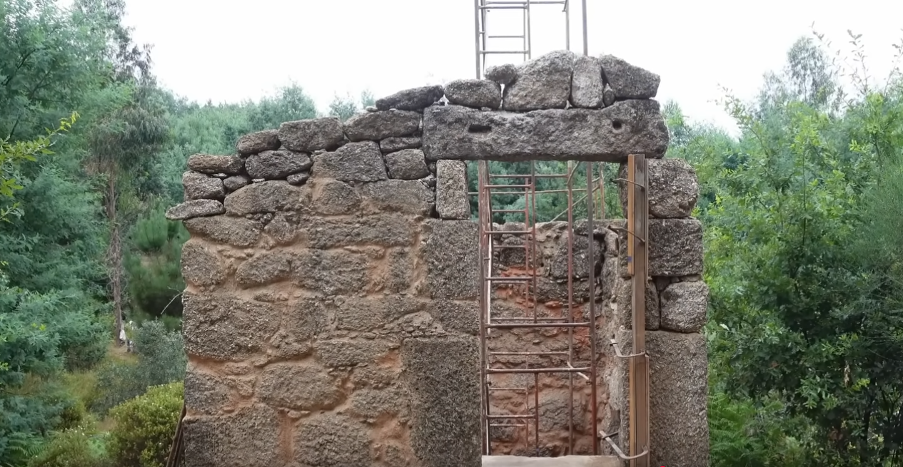
What is the state of the ruin?
Published 2yPublished about 2 years ago
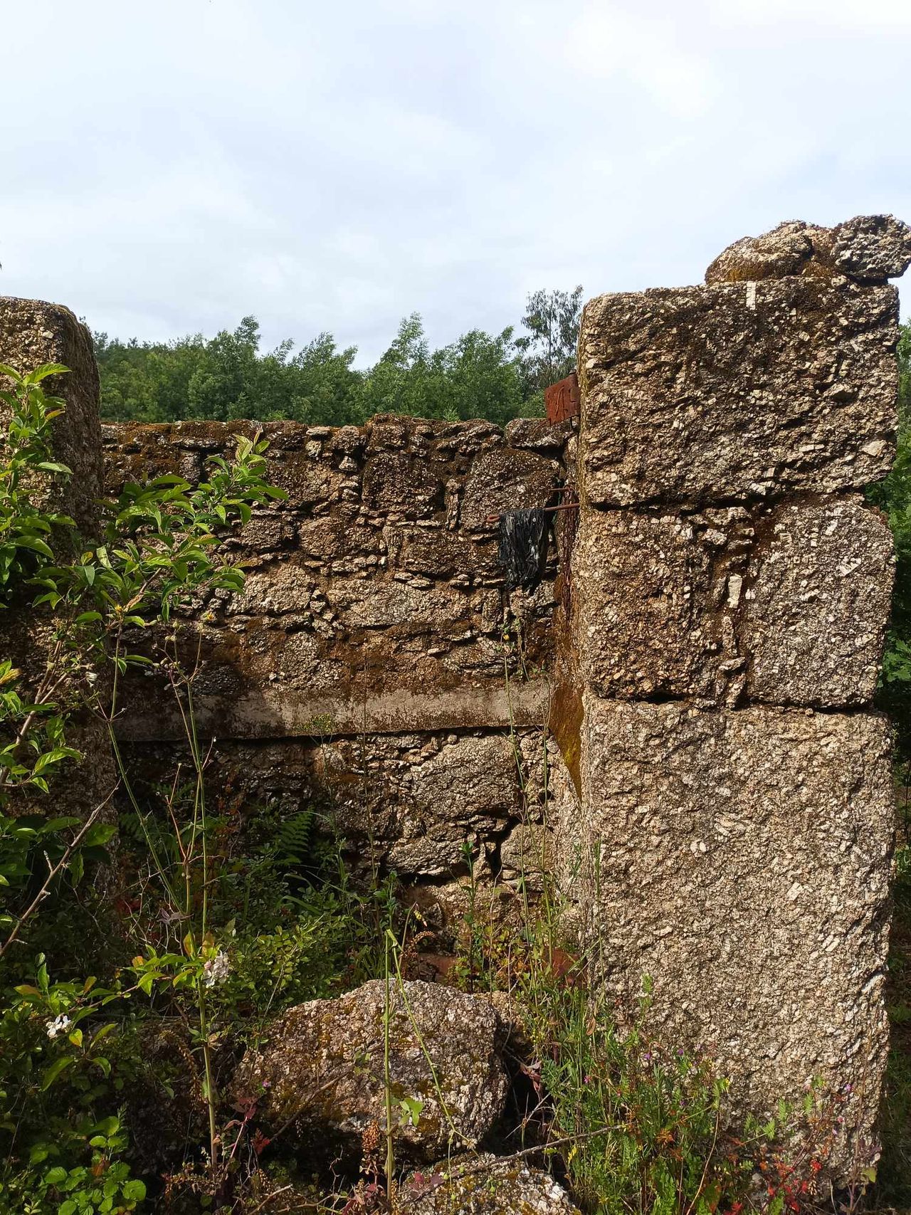
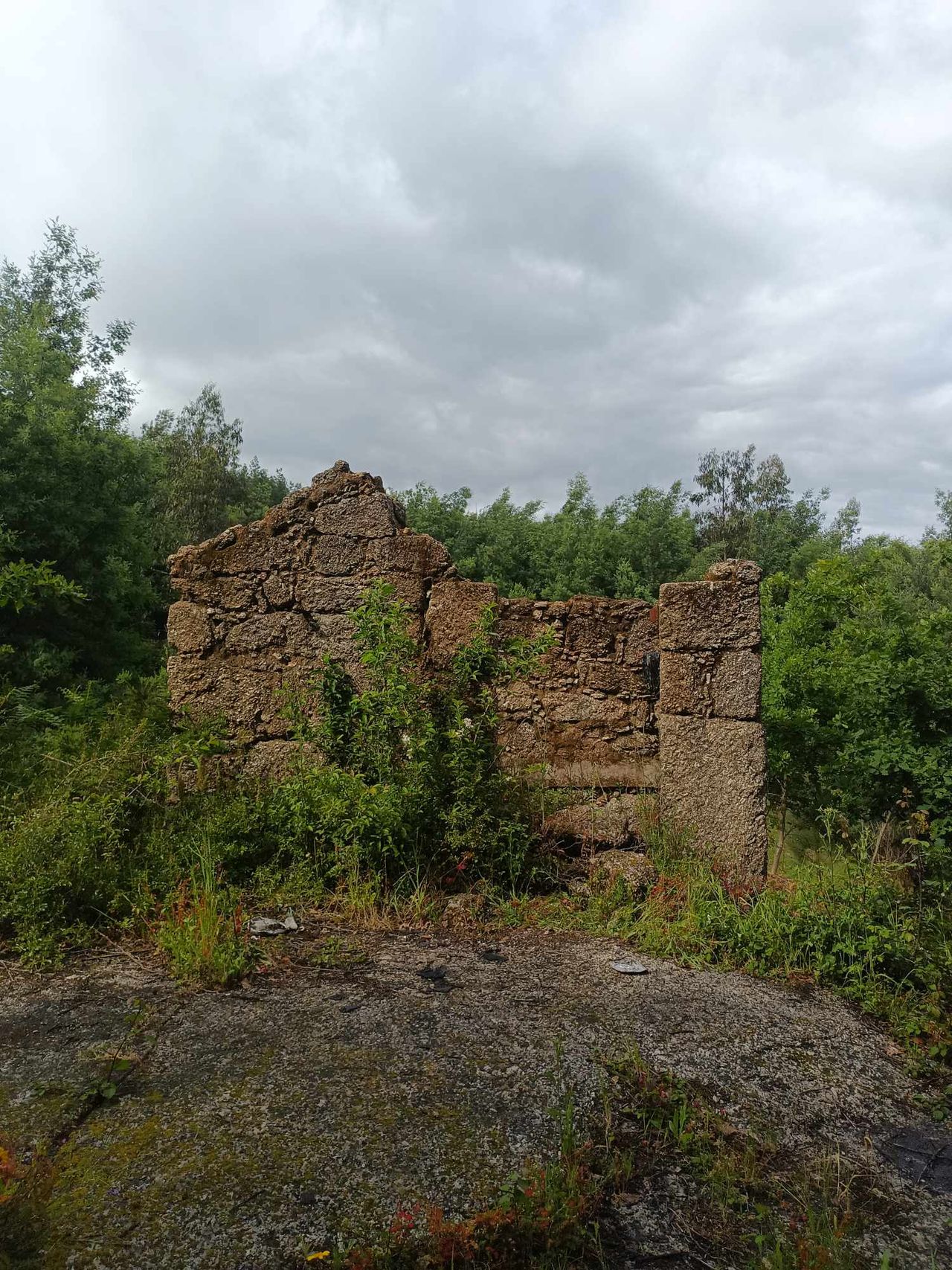
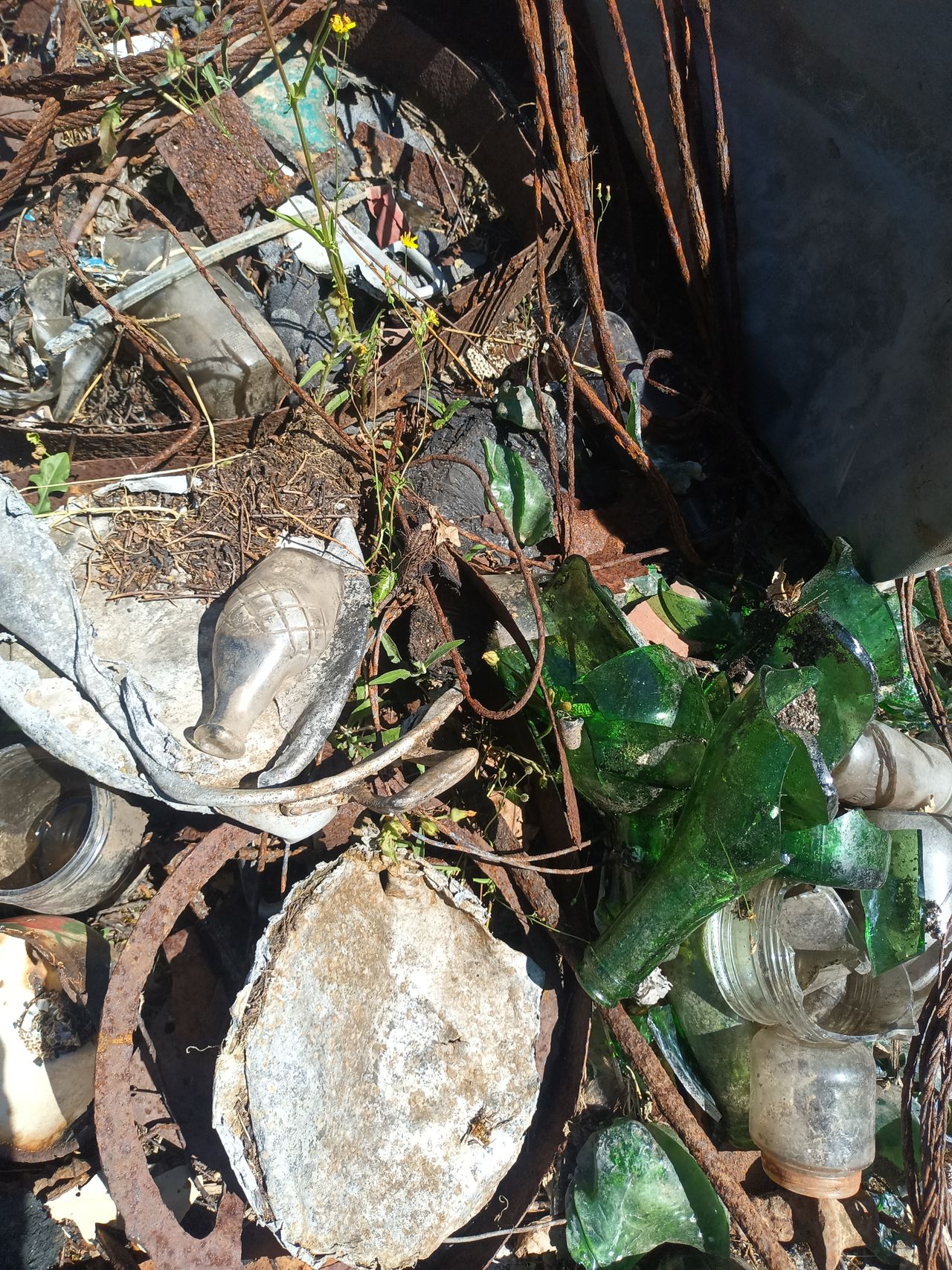
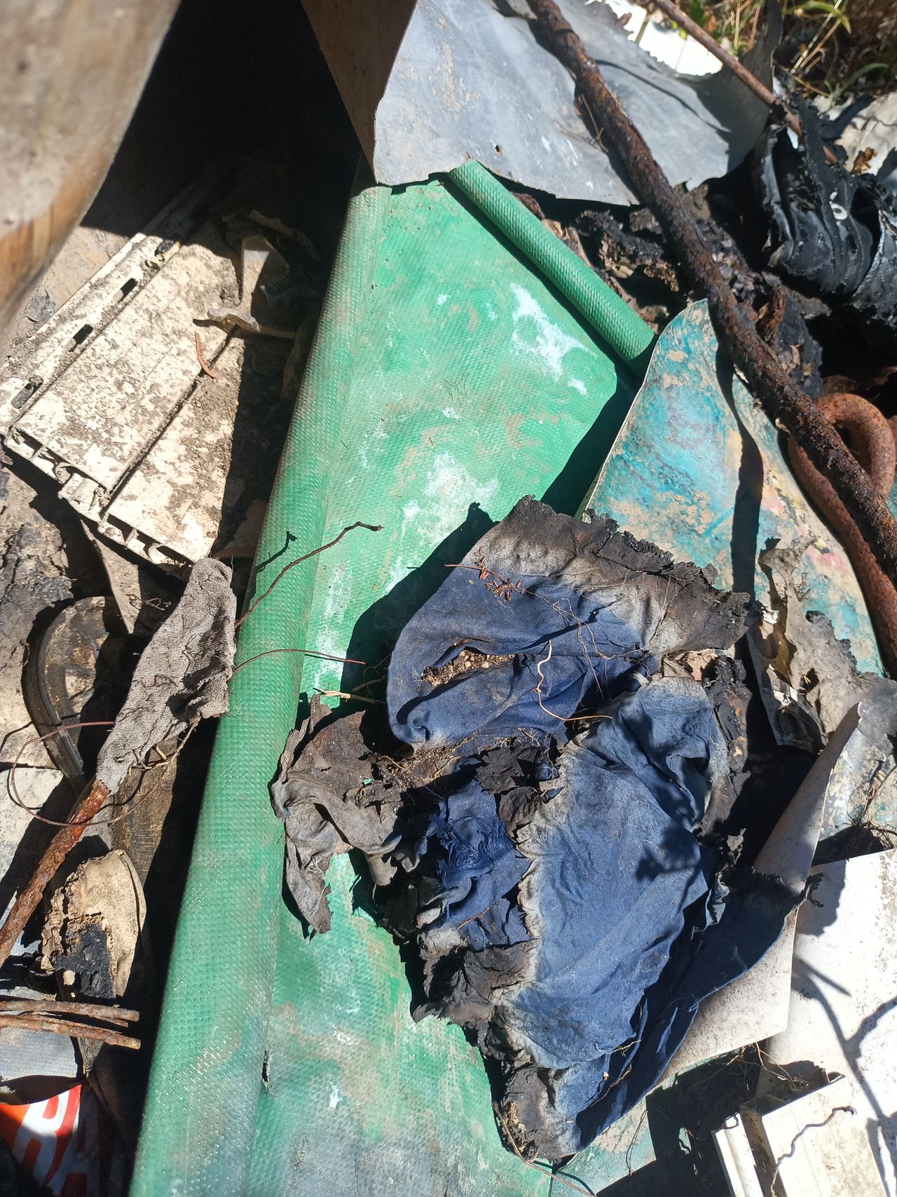
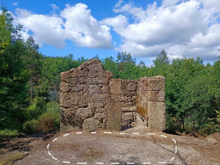
The granite ruin, which apparently used to be a donkey house, seemed to be two floors. We found some hinges, a very rusty key. We can also tell from the fallen burnt beams that the main structure was made out of wood. There are two entrances, one on the bottom floor (donkey door?) and one on the top floor (farmers entrance for storage or kitchen?). An architect is coming at Kamp soon to examine and see the best way for us to renovate this ruin. Before he arrives, we want to learn more about how to renovate with granite. So if you have any knowledge about it, this research module is the right place for it….

2
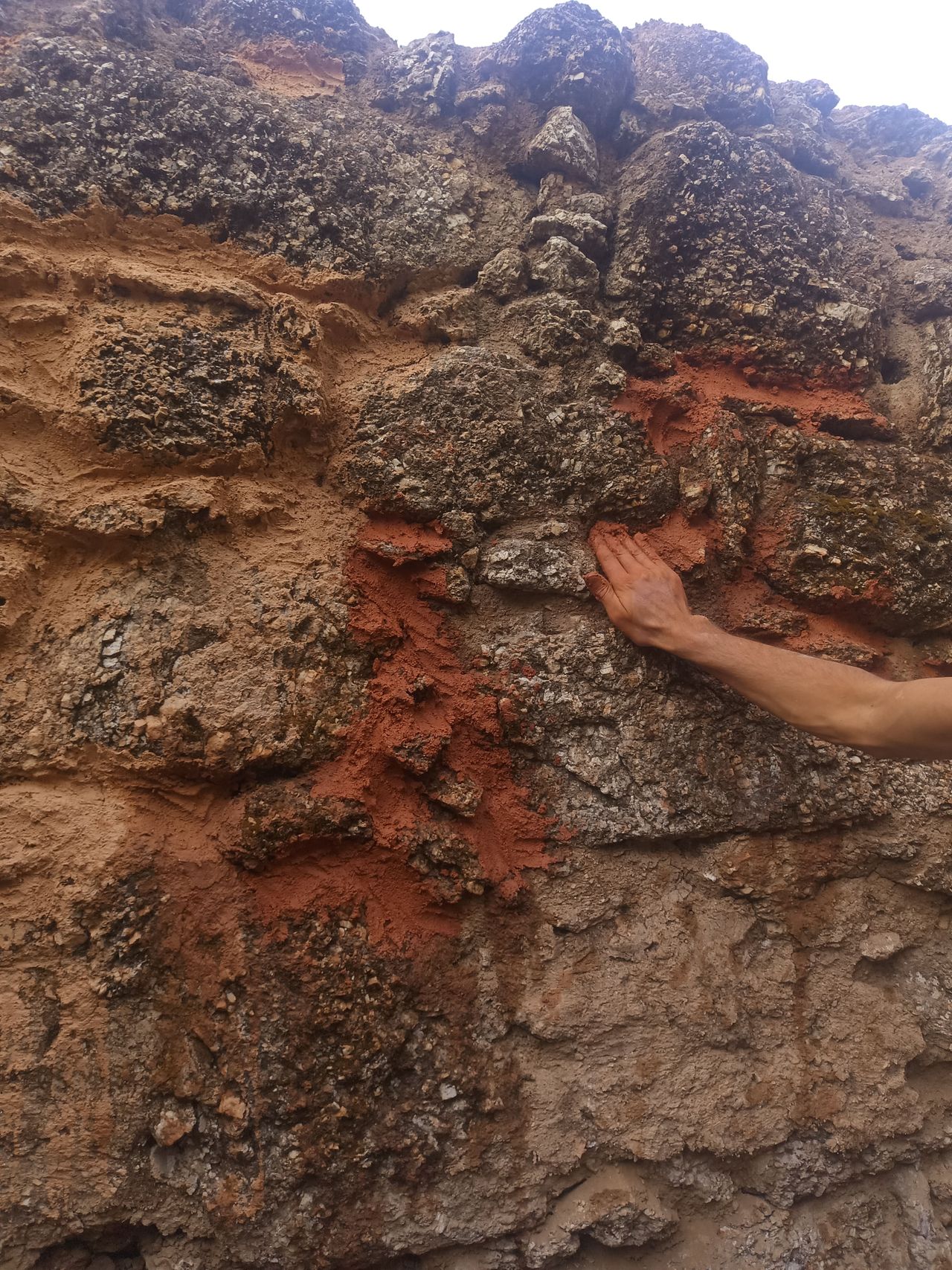
Decomposed Granite "GRUS"
Published 2y. Edited 1yPublished about 2 years ago. Last edit about 1 year ago
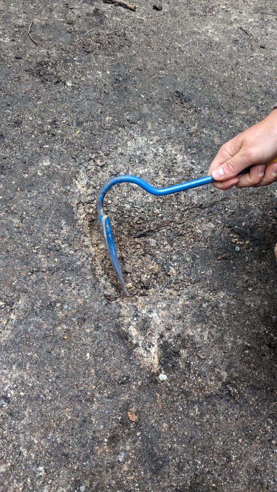
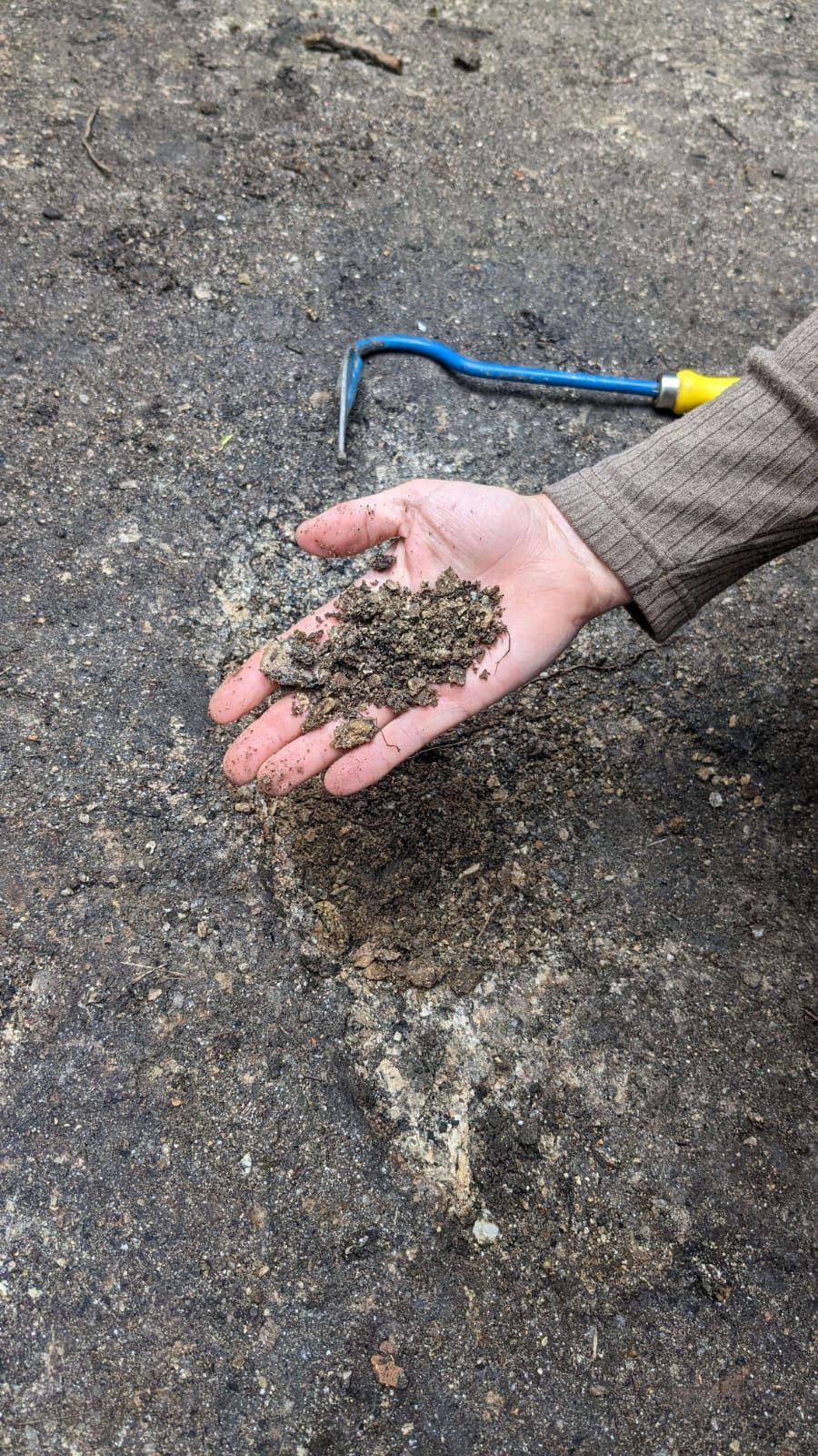
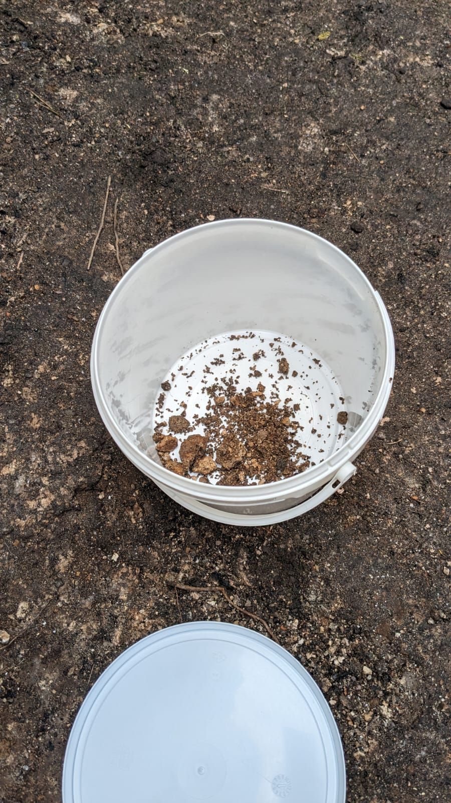
While cleaning the ruin, we encountered a big granite stone floor. Only one problem, the stone floor seemed super brittle, like we could have dug it out with shovels. Could the stone have been rotting? Our guess is that we are dealing with decomposed granite. “grus”. The wikipedia is quite instructive about it: here is the link: https://en.wikipedia.org/wiki/Decomposed_granite Apparently, granite is made of 3 main rocks and one of them can rot, transforming into silica and clay, crumbling down into a gravel sized weather rocks. It is apparently used for petanque floor, alley, pavement, driveway, pathway,... One of us suggested that we could try to use the falling silica and clay (kaolin?) and make it into a mortar, maybe even the mortar we would use to renovated it. that would really be a cool way of re-using a crumbling down wall…
3
Clearing of the ruin
Published 2yPublished about 2 years ago
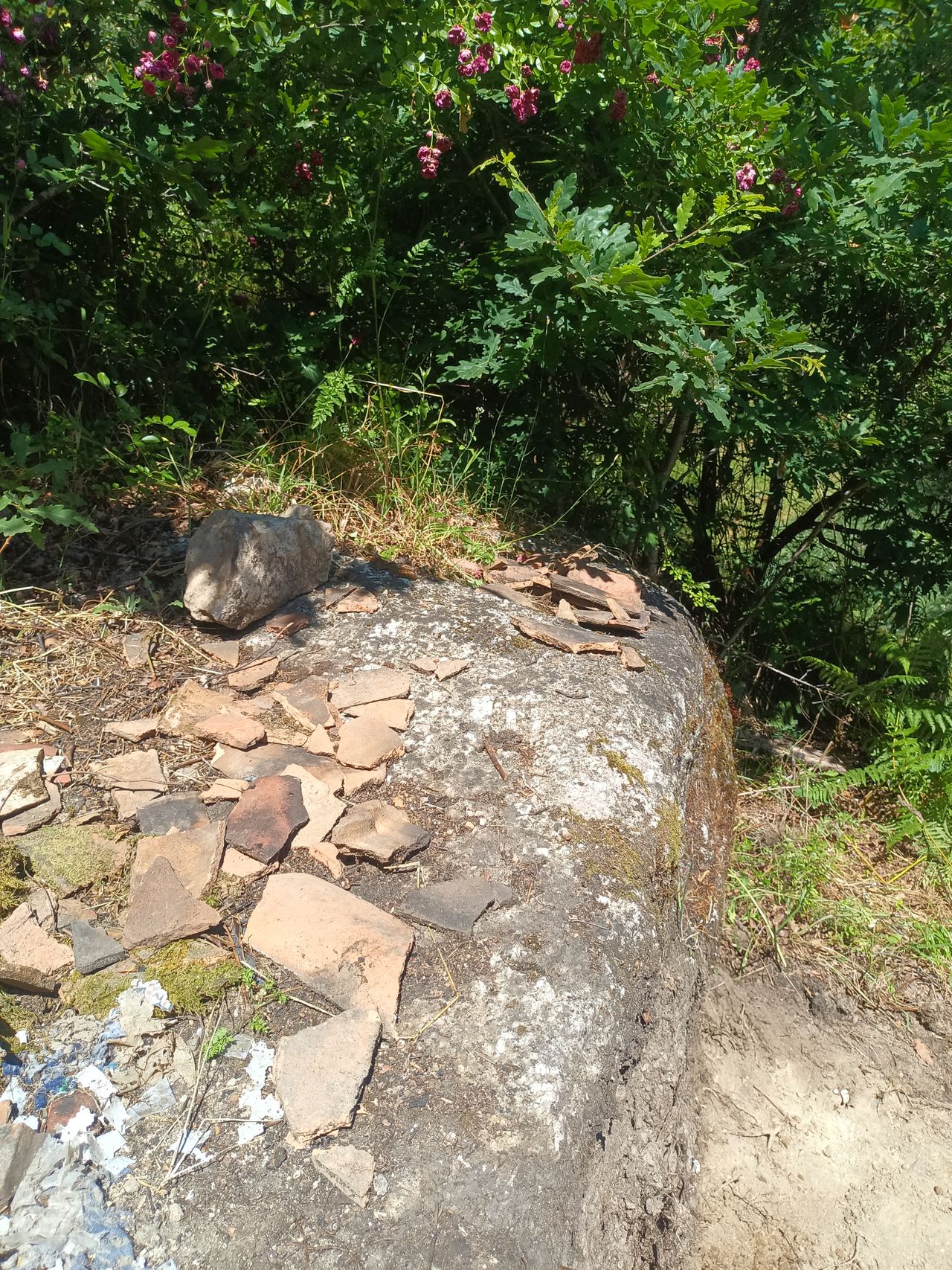
To properly see the ruin, we need to take it out of the brambles, piles of earth and leftovers tiles and burned things from the fire. The whole structure has been taken over by vegetation, preventing us from having a good look at it. Clearing with shovels and brooms will allow us to take measures, get a better idea of the floor relief, understand the use of it from the previous owner, maybe reveal some secrets…
4
Where is the ruin on the land?
Published 1yPublished almost 2 years ago
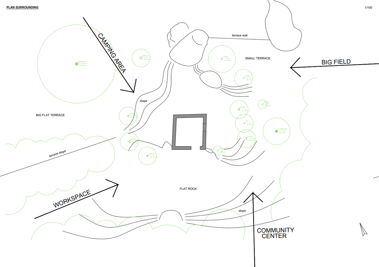
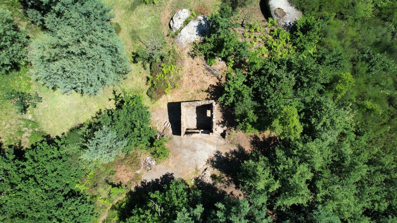
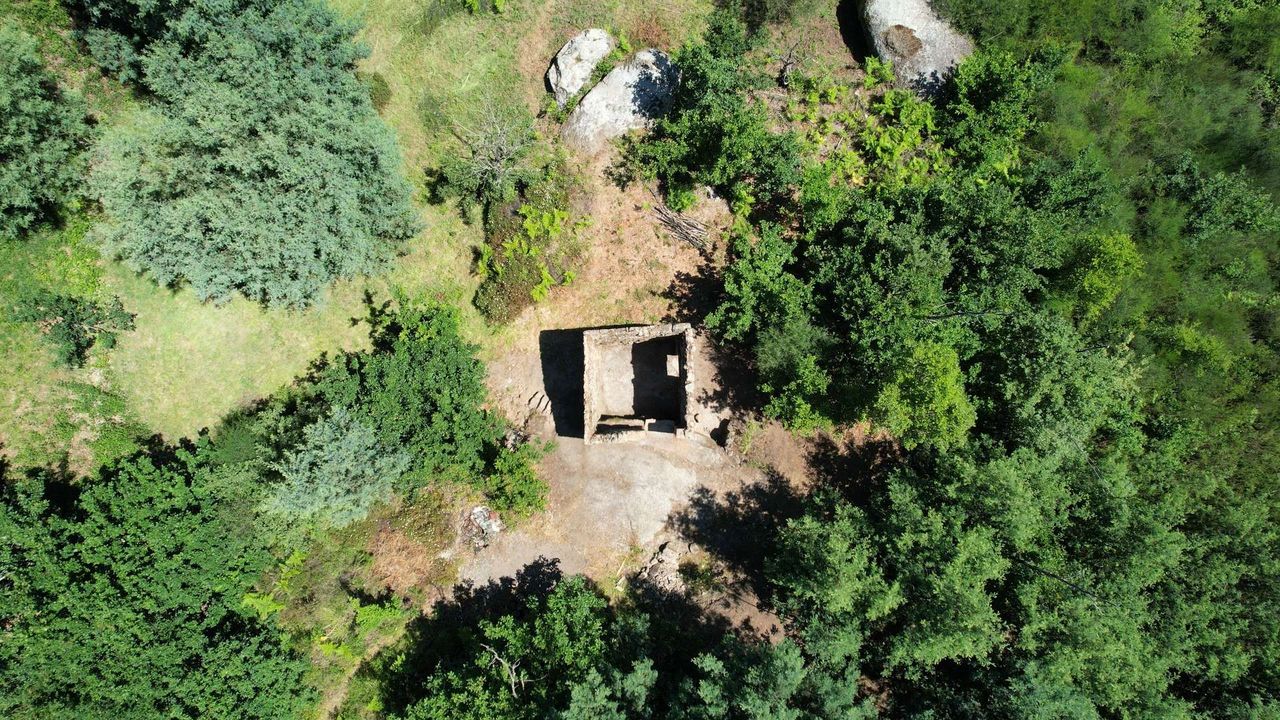
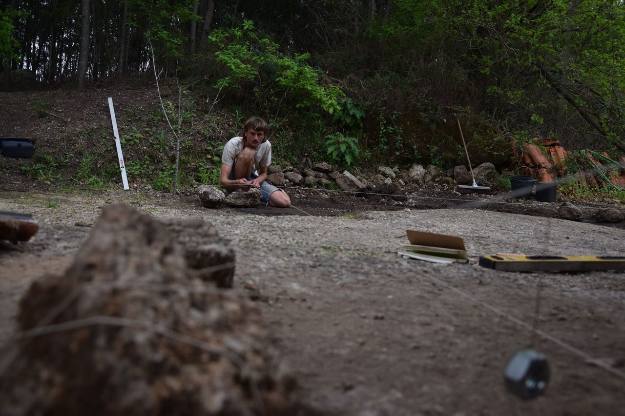
Before we can get started on the design of the renovation and therefore deciding which programme fits this ruin, we want to have a better overview of where the ruin is located and how it will be connected to the rest of the land. We made a survey of the surrounding area including the most important trees nearby, the big characterful rocks and the terrain with its height differences. Next we marked the most important connections with the rest of the land. The community center will be 50m to the south, the future workspace area (now basecamp) will be in the west. In the north, on the different terraces of the middle land close to the ruin, the camping area will be located for all the volunteers and visitors coming to help out in Project Kamp. If we go east the land slopes a lot towards the big field that sits on the bottom of the land.
5
Which spaces are good for which programme?
Published 1yPublished almost 2 years ago
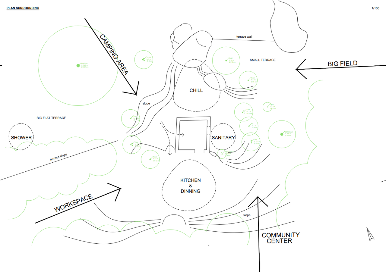
The middle land will become the main camping area for all the volunteers. Therefore we want the ruin to be the support building for this programme. Call it a tiny basecamp. This will include an outdoor kitchen, places to hangout and relax indoor and outdoor and a sanitary area.
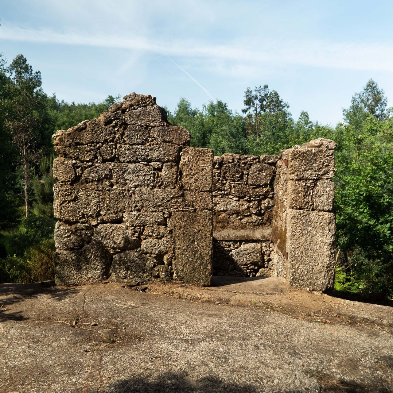
In the south side of the ruin sits a big flat rock, it forms a natural stone terrace. This area will also make the connection with the community center and the workspace so it makes a great place for a central programme, the heart of this new place: The outdoor kitchen and dining area. The north side has a smaller flat area ending in a big theatrical granite rock. On the east side of the rock there are two small terraces with small oaks making this area great to relax and hang out. The east side is the most out of sight, covered also by a few oaks and a cork oak. We find it a great place for a sanitary sink for brushing teeth, etc. Now that we have a better idea of the programme, we can go ahead with the design.
6
What are the constraints when renovating this ruin?
Published 1y. Edited 1yPublished almost 2 years ago. Last edit almost 2 years ago
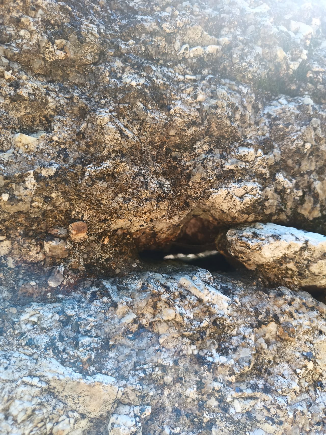
Renovating an existing building always comes with certain limitations that have to be taken into account during the designing process. Here for example we face two major constraints. The first is the fact that the ruin is built on and half into a rock. A choice that is typical for these old ruins as it gives the builders a sturdy rock foundation without the need to dig and with the rock they get a ‘free’ first wall. The result is that it’s hard to keep the groundwater out of the building as it seeps through the side of the rock, limiting the options of what the bottom floor can be used for. Traditionally these ruins are built with the intention of using the bottom floor as a stable, therefore they didn’t mind this disadvantage back in the day. We will have to take into account the possibility of groundwater entering the building. To make sure the water can go away there is the need to include a proper drainage layer in the floor. As a result the usable height of the ruin is reduced by the thickness of this drainage layer.
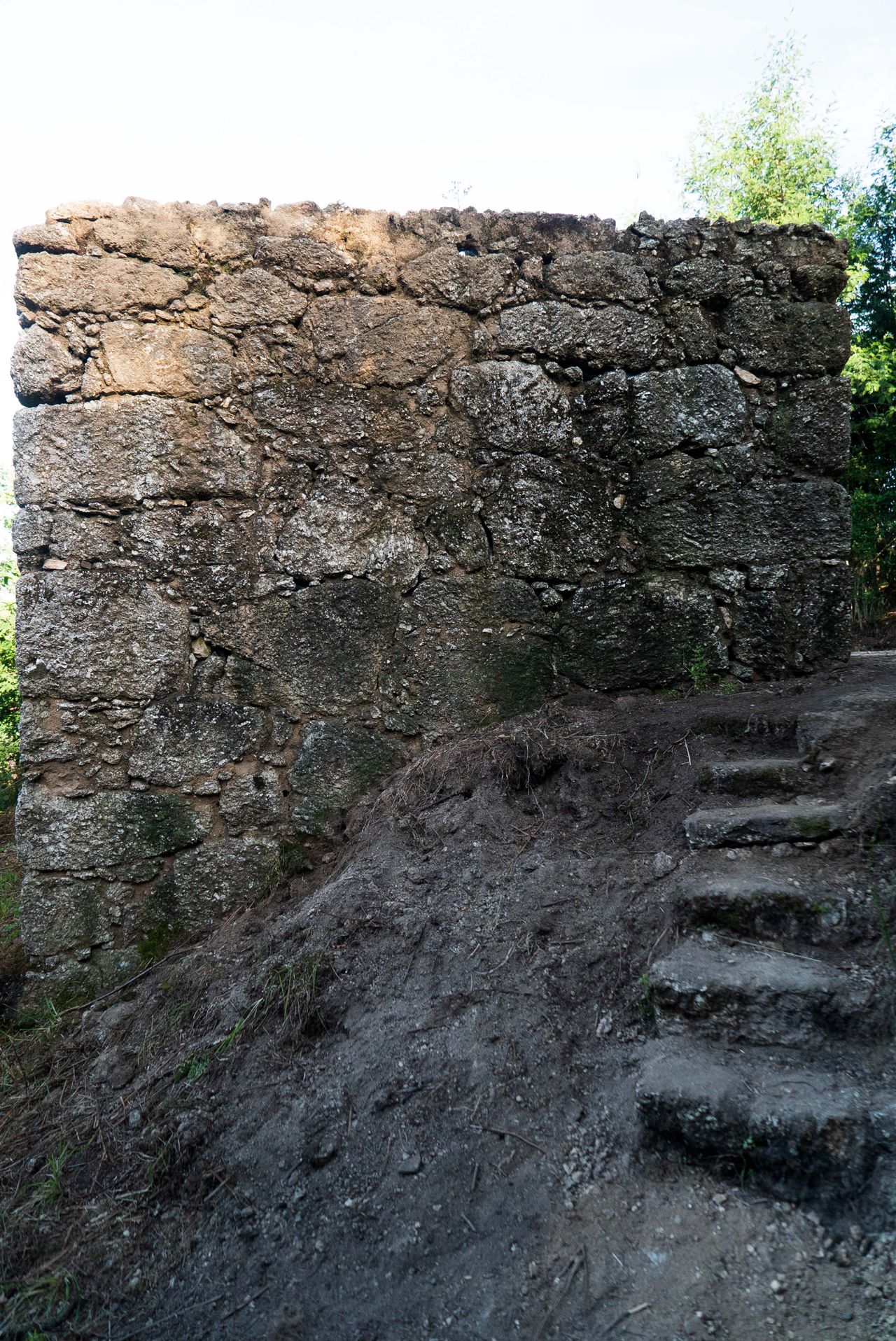
A second constraint is the structural limitations of the existing structure. This small ruin isn’t built with very thick granite walls as the larger ruin, as they didn’t intend to go any bigger than the current one and a half floors. Bigger ruins in the area typically have wall thicknesses of around 60cm. Whereas here the walls are (only) 35cm on average. This limits us to go much higher with the existing walls without an additional structure.
The ruin has a total height of 350 cm at its highest point. The first floor used to be 140cm high. Leaving only about 120 cm of usable height at the bottom floor and about 200 cm of usable height at the upper floor. You would need about 230 - 260 cm of usable height to create a qualitative living space. We see two main options to move forward:
A first option would be to rebuild the floor and roof at its original height
+ there is no need for an additional structure to build the ruin much higher
+ we can reuse existing doors/openings
+ possible to finish this season? Which means it could be used this winter
- bottom floor is not very usable, except for long term storage or technical installations
- not using the ruin to its full potential, by not creating optimal indoor spaces
A second option would be to rebuild the in-between floor about 90cm higher and extend the walls about 120cm.
+ two usable indoor spaces (=double the usable surface), using ruin to its full potential
- the need to create a new door opening for the bottom floor
- the need to build up the walls higher, therefore having to at a new structure
- less realistic to finish this season…
You can download the plans of the existing structure here and watch the update #117 to see how we cleaned the ruin and took the measurements.
%20--%3e%3csvg%20version='1.1'%20id='Calque_1'%20xmlns='http://www.w3.org/2000/svg'%20xmlns:xlink='http://www.w3.org/1999/xlink'%20x='0px'%20y='0px'%20viewBox='0%200%2027.2%2027.8'%20style='enable-background:new%200%200%2027.2%2027.8;'%20xml:space='preserve'%3e%3ctitle%3eicon%20redirect%20new%3c/title%3e%3cg%3e%3cpath%20d='M27.2,26.5c-0.1-5-0.3-10-0.4-15c0-0.7-0.6-1.2-1.2-1.2s-1.2,0.6-1.2,1.2c0.1,4.6,0.3,9.1,0.4,13.7%20c-3.9-0.2-7.7-0.6-11.6-0.4c-3.3,0.2-6.7,0.5-10,0.4C2.8,19.5,2.7,13.7,2.5,8c2.9-0.1,5.8-0.8,8.6-0.7c1.6,0.1,1.6-2.4,0-2.5%20C7.8,4.6,4.5,5.7,1.2,5.5c-0.6,0-1,0.3-1.1,0.7C0,6.3,0,6.4,0,6.6c0,0,0,0.1,0,0.1c0,0,0,0,0,0.1c0.2,6.6,0.4,13.2,0.5,19.7%20c0,0.6,0.4,1.3,1.2,1.4c3.8,0.1,7.5-0.2,11.3-0.4c4.4-0.3,8.6,0.2,12.9,0.4c0.6,0,1-0.3,1.1-0.7C27.1,26.9,27.2,26.7,27.2,26.5z'/%3e%3cpath%20d='M12,12.6c-0.2,0.7,0.2,1.4,0.9,1.5c0.7,0.2,1.4-0.2,1.5-0.9v0c0.6-2.2,1.4-4.5,3.1-6c1.3-1.2,3-1.9,4.7-2.7%20c-0.4,1.3-0.8,2.6-1.4,3.8c-0.6,1.5,1.8,2.1,2.4,0.7c0.8-1.9,1.5-3.9,2-5.9c0-0.1,0-0.2,0-0.3c0.3-0.6,0.1-1.5-0.7-1.8%20C22.3,0.4,20,0,17.7,0c-0.7,0-1.2,0.6-1.2,1.2s0.6,1.2,1.2,1.2c0.9,0,1.7,0.1,2.6,0.2c-1.7,0.8-3.4,1.7-4.8,3%20C13.6,7.6,12.7,10.1,12,12.6z'/%3e%3c/g%3e%3c/svg%3e)
7
How we came up with a new design
Published 1yPublished almost 2 years ago
After some research and designing the different possibilities for the renovation of the ruin, we decided to go for the option where we don’t have to add an additional structure to the existing granite walls. Many different things are taken into account when taking these kinds of designing decisions. In our current situation we weighed the pro’s and con’s and decided that the extra work and complexity of an additional structure was not worth the resulting benefit of having the extra space. Therefore we went with the option to have 1,5 floors, with the bottom floor being too low to stand up in, just like it used to be.
We now know the final height of the ruin, which functions we need and where we would like them (see update 5) and we have the survey of the existing situation digitized. With all of this information we can go to the drawing table and create a new design for the granite ruin.
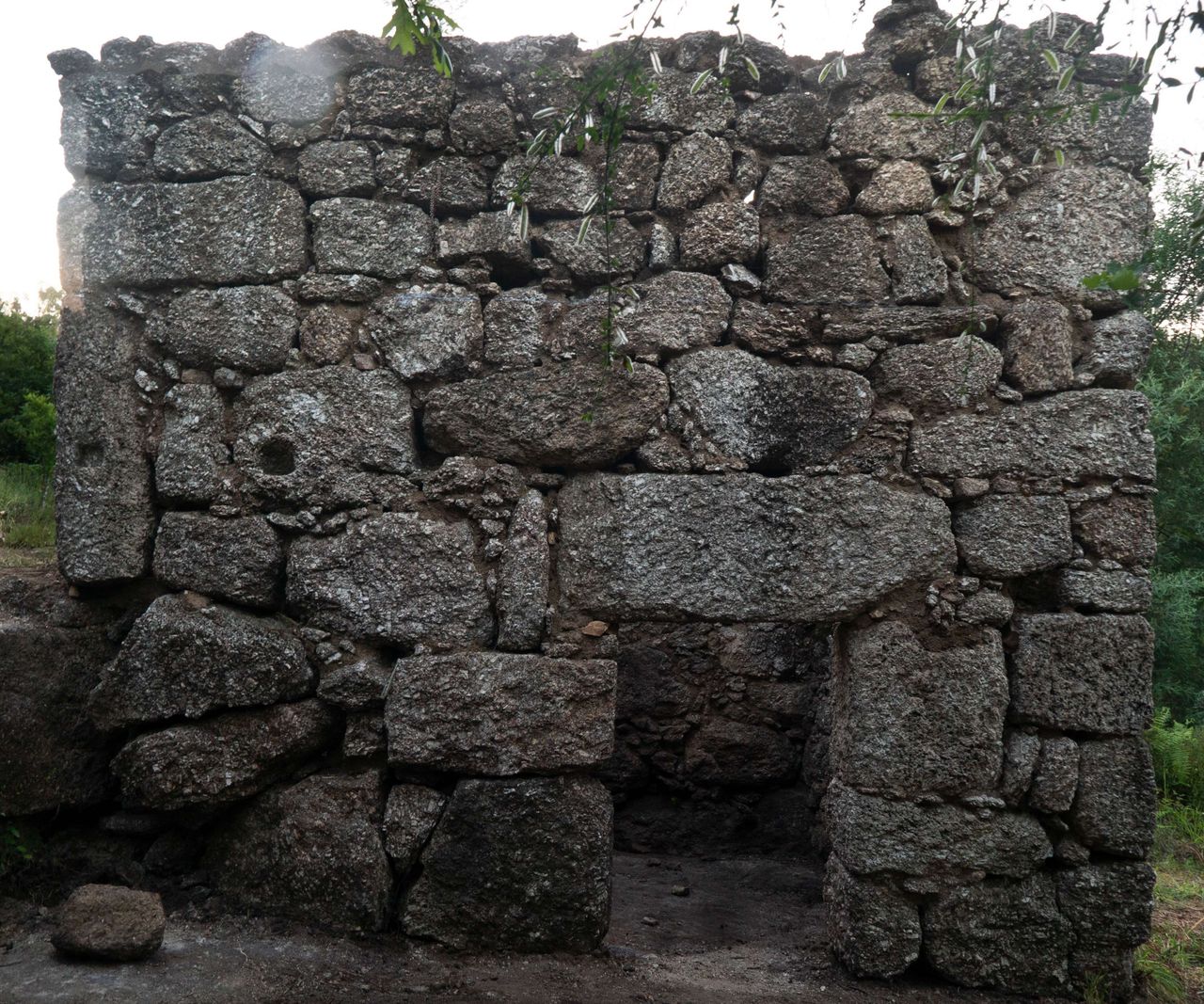
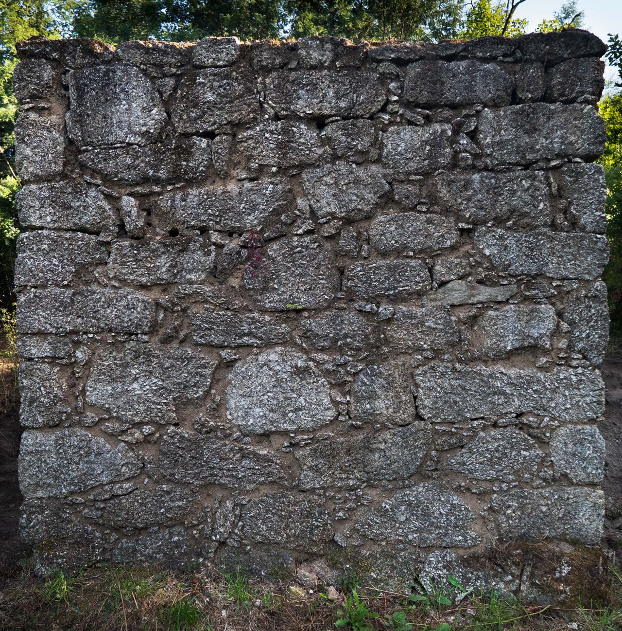
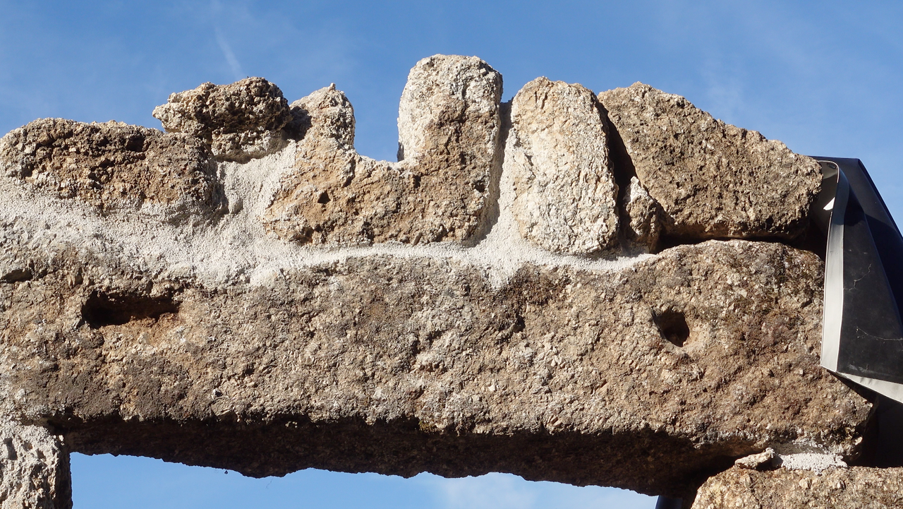
The existing structure seems like a square, but in reality there are no straight corners. Most of the walls are rather straight, but on the east side the top part of the wall (above the small entrance door of the bottom floor) the wall is bulging outwards. We notice that the stones here are smaller and the triangle shape of the south facade tells us the roof was probably sloping towards east and west. The weight and outwards pressure of the roof on this wall probably made the wall bulge like this. We will have to rebuild this part of the wall to make it structurally solid.
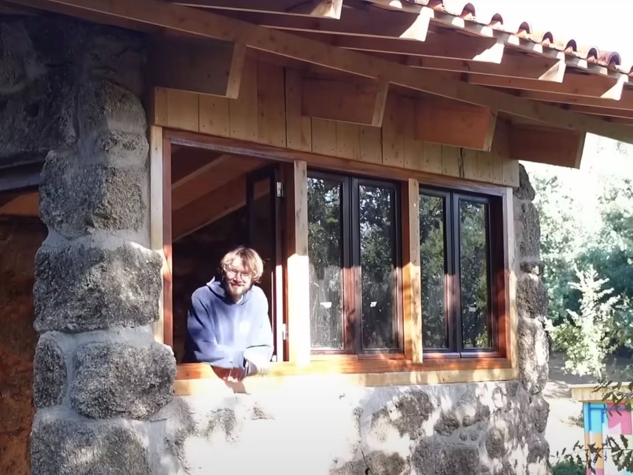
The top floor only has an entrance door and no other windows, so we want to add additional openings in the facade to allow more natural light to enter the building. The east side of the building is in our case an interesting place for a new window since it has the nicest views of the land. On top of that, sunlight entering through the east facing windows could help heating up the building after cold nights. Therefore we decided to not rebuild this part of the east wall, but to replace it with a large window. We found some nice wooden windows from a neighbor who replaced the windows in his house and integrated them into the design. Besides the new opeing we can reuse the two existing doors on the two levels.
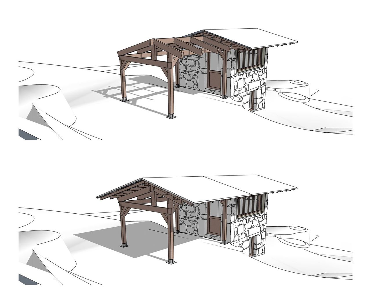
Next element to think about is the roof. We know we want to reuse roof tiles which means we have to create a sloped roof of at least 15 degrees to have the water run off smoothly. We wish to extend the roof towards the south of the ruin to create a covered outdoor kitchen and dining area, resulting in a rectangular shape. We slope the roof along the longest side of the rectangle to make sure the roof doesn’t end too low and we put the top of the roof (the ridge beam) a little out of center of the ruin so the roof is ending higher on the east side than on the west side. This allows us to benefit from more natural light entering the windows on the east side.
8
Building up the walls
Published 1y. Edited 1yPublished about 1 year ago. Last edit about 1 year ago
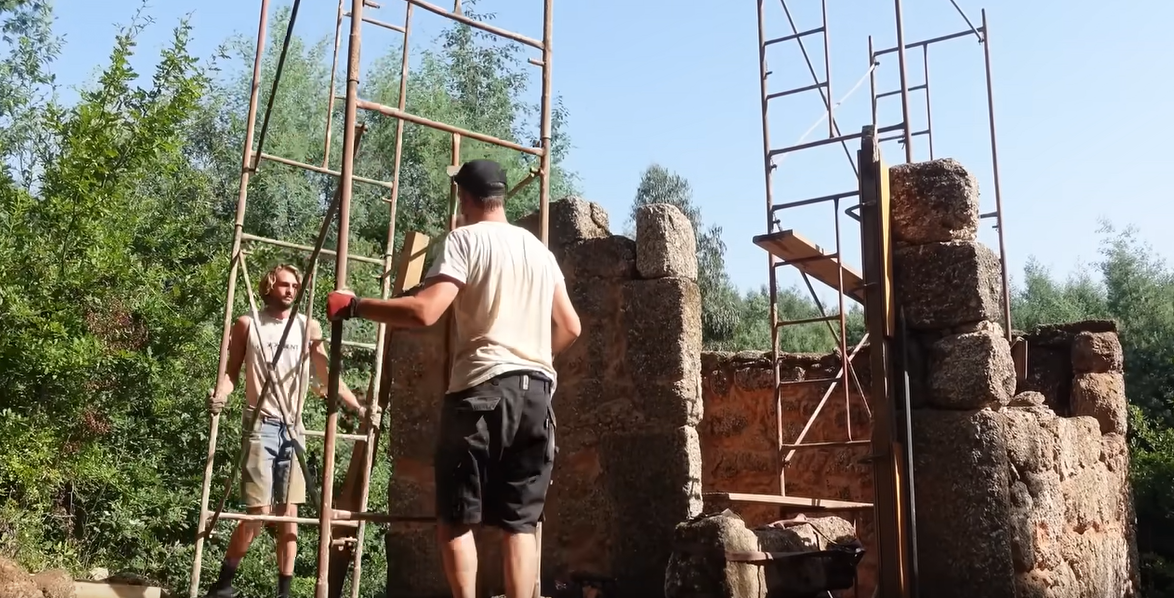
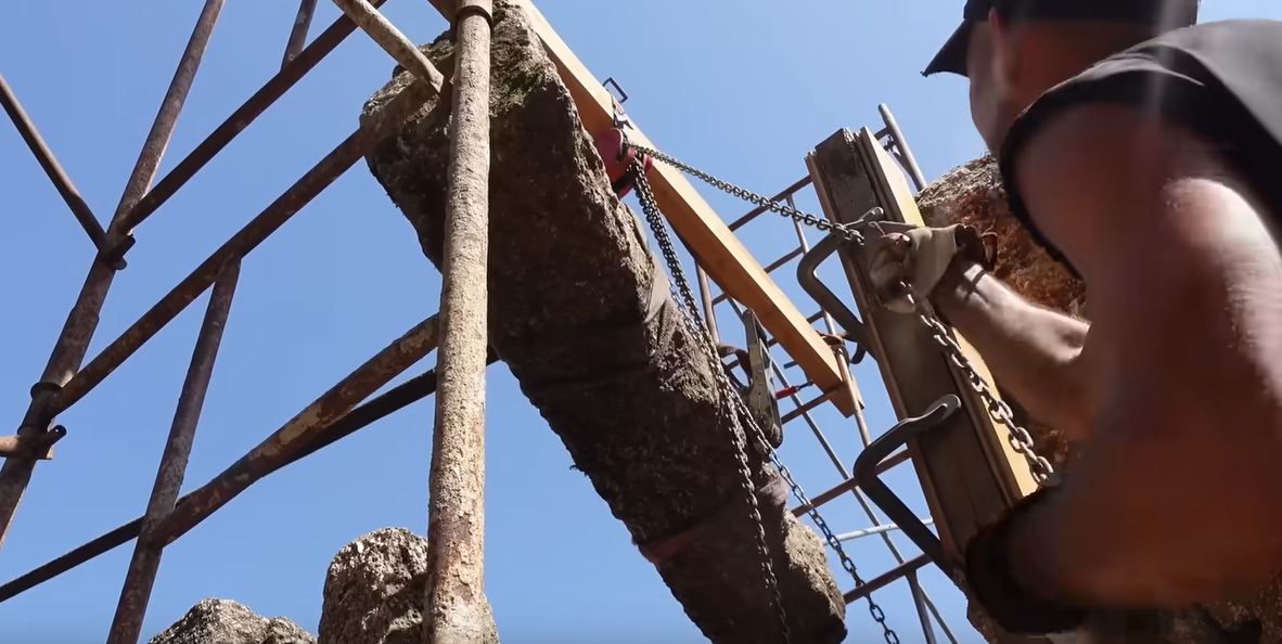
We now have a Design, a clear plan. To follow the schematics, we need to raise the walls higher.
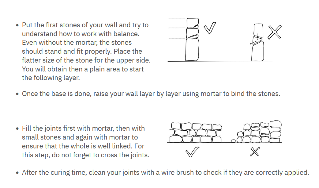
Continuing in the same style of the granite ruin, we are going to stack the stones “dry” (without mortar in a first place) to make sure our structure is solid.
A dry wall is a wall that stands on its own just by the position of the stones and how they connect. The drawing made by critical concrete helps understanding how they are built. We made a research module about how to renovate granite walls to go more in depth. There you will find the whole detailed process of the refurbishing of the granite walls.
https://community.projectkamp.com/research/can-we-renovate-granite-walls
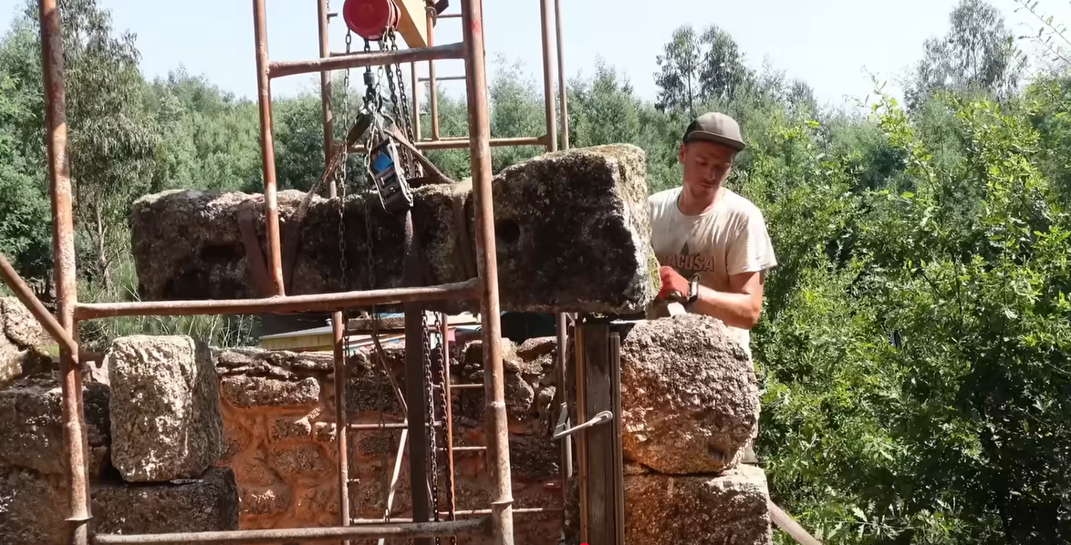
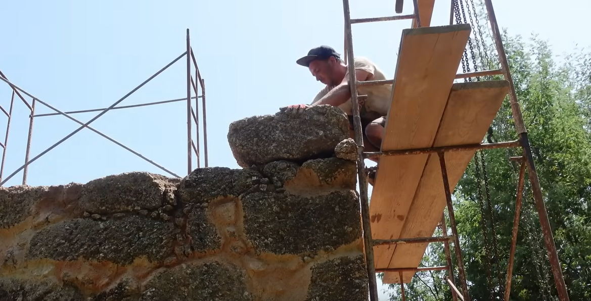
The secret of a good dry wall is the wedges. Making sure that the stones you are putting in place will not move, no matter what. For that, you can use wedges. Often times the wedges you use will be another smaller stone that help the big stone to sit stable, but it can also be that you will need to chisel the stone below to have a perfect fit.
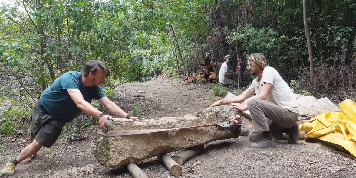
This is the video of us building up the walls. Quite physical labor with a chainlift to bring the stones higher than the walls.
https://www.youtube.com/watch?v=v2nCRUa94EA&t=797s
Once we put the stone where we needed them to be, it was time for...
9
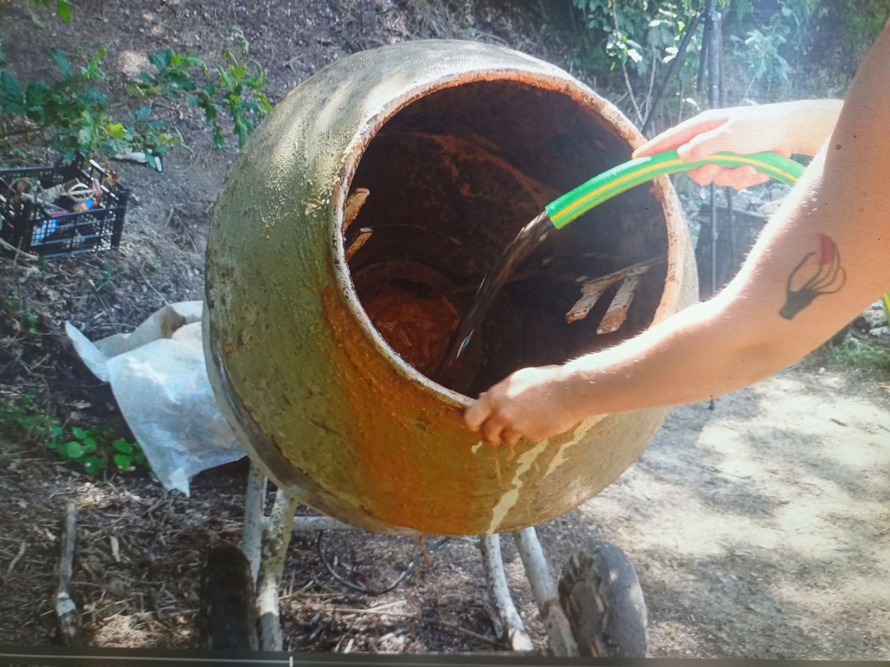
Clay and Sand Mortar
Published 1y. Edited 1yPublished about 1 year ago. Last edit about 1 year ago
The dry wall is up and standing strong. But the air is going through so our next move is to make the wall airtight. For that, we are using clay and sand mortar.
The first step is to make sure our walls are ready to welcome the mortar. We are going to brush all the moss out of the old stones, scrap the old mortar and make sure nothing wants to fall out or crumble of the walls.
Our ratio was 1 clay, 3 sand and some water to get our mixture playdo-ish, you want a texture thicker than yogurt. The less water is in your mix, the less retraction and cracks you will get, so it is a matter of being on the edge of humid but not too humid, workable by hand but not wet. If you are wondering how to make your own ratio, you can go on the research module about how to renovate a granite wall, ther you will find more detail about those steps and what kind of test to make.
https://community.projectkamp.com/research/can-we-renovate-granite-walls
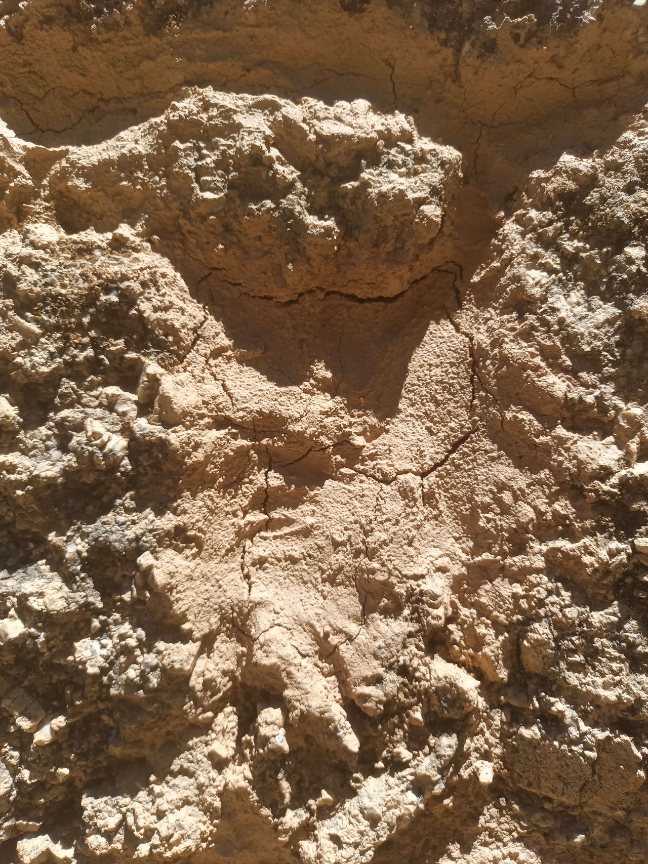
Once your mix is made, wet your wall. Then we come and put the mortar to fill all the holes from outside and in. We did a sort of meticulous job on the outside (because we want nice lime joint finishing outside) but a very sloppy job on the inside (because we already know we are going to make a plastering also out of clay after ward so we didn’t need to be too tidy.
We use our hands to shove the mortar inside the hole left by the joints between the stones. You want to have filled your wall enough that no air remains inside. And sometimes, that means taking a handful of mortar and splashing it on the wall. Throwing the mortar is great because it garanties you that it took all the air out. And that is very fun. Work from top to bottom in order to not have you mortared wall being wet again and again…
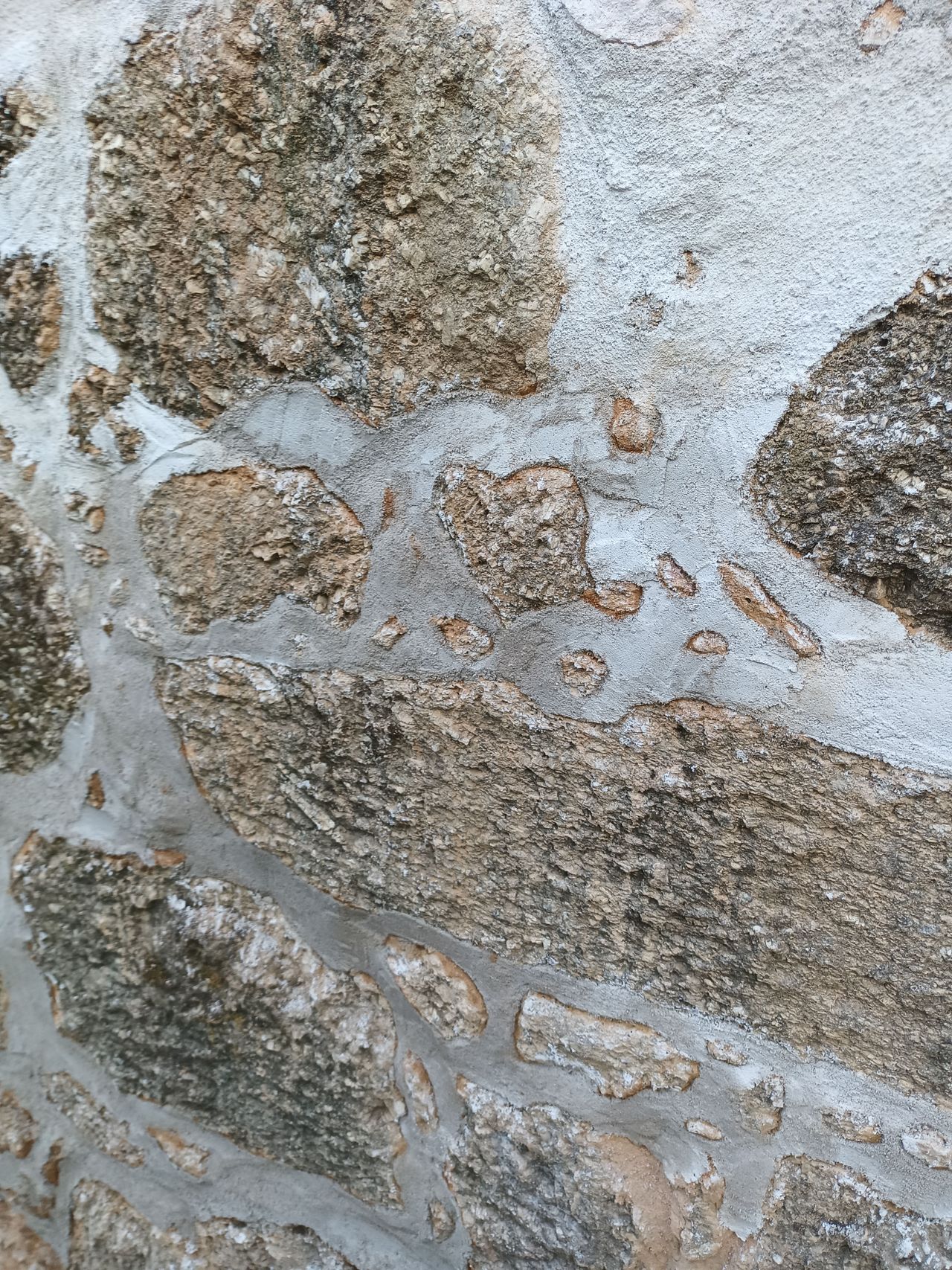
If your mortar is cracking (picture 3), that means that there isn’t enough sand in there. No need to start all over again, wet it again and come with your new sandier mortar and wedge it in!
10
Outside lime joints
Published 1y. Edited 1yPublished about 1 year ago. Last edit about 1 year ago
The clay and sand mortar that we used to make our walls airtight isn’t very resilient to direct water like rain so they need outside protection, the inside will be protected by the roof.
To protect our clay and sand mortar while still enjoying their mechanical properties (breathable material, keeping the humidity in during the cold months and releasing it when it is hot, making the inside of the house cooler ((yes it is awesome)), we are using lime joints.
We are going to make lime joints between the stones on the outside and protecting our mortar. Once again you can check out our research module about how to renovate a granite wall where you will find more in depth research about lime work. https://community.projectkamp.com/research/can-we-renovate-granite-walls
Working with lime requires equipment for safety like glasses, gloves and dust masks!
The ratio we used is 1 of lime for 2,5 of sand and add water little by little until you obtain a mix that has the same consistency as the clay mix.
You have made your lime mix.
It is now time to repoint your wall: making those precise lime joints on the wall. Much like clay, lime needs a wet surface to grab. So we are back with our water bucket full of sponges, brushes and other tools we found on the way. For this step, you will need a very thin trowel to push the lime in narrow corners. Just like with the clay, we work from the top and make our way down.
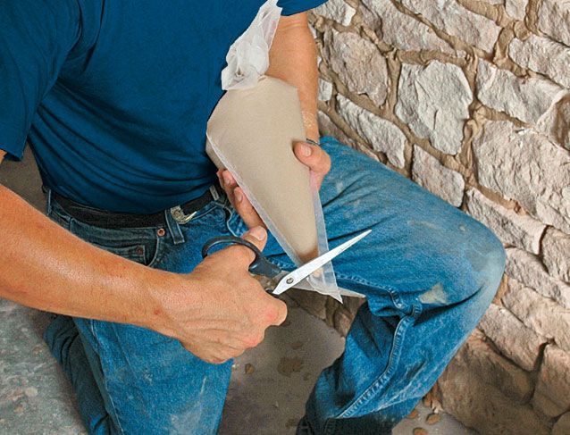
You can also use one of those pouches that bakers use to push the lime mix into very intricate corners.
You can come in a second time when your lime is leather hard to come and smooth it better for a prettier outcome.
The lime dries for a longer time than cement and prefers not to hot temperature to take properly, between 05 and 25 degrees.
Here is the video we made, lime work is 24 minutes in: https://www.youtube.com/watch?v=u-TZUopTH1U&t=1726s
Once we finished our wall it was finally time for...


11
Floor frame
Published 1y. Edited 1yPublished about 1 year ago. Last edit about 1 year ago
Now that the walls are erected, it is time to proceed with the next steps. Since the bottom of the ruin isn’t flat, we decided to start with the floor, since this will allow us to work comfortably with the scaffolding
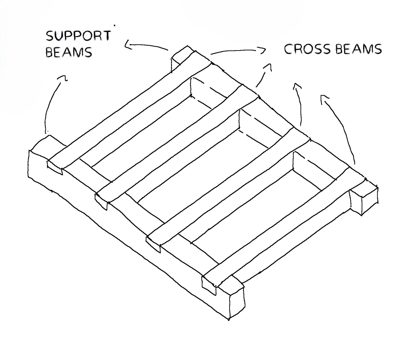
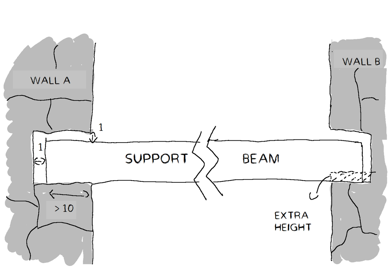
The chosen floor structure is shown in picture 1.
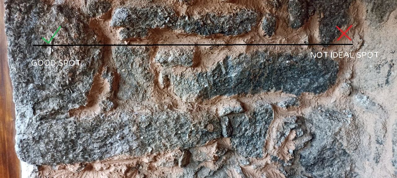
Two of the beams are notched into the wall (support beams) providing a physical connection with the structure, while the other (cross beams) provide support for the floorboards. These are joined through a cross lap joint. Another solution could have been to use only cross beams directly notched into the wall, but this requires a lot of work to make the holes, tricky to make them at the same level and to find good and stable granite rocks at the same level. Here is an example (picture 2), chosen as reference the black line, the right side has only small rocks, not suitable to carry a load.
First we started with the support beams.
Starting from one side (wall A, picture 3) we made a notch in the granite stone with a depth of at least 10 [cm], leaving a bit of space around the beam to promote airflow, in order to reduce the risk of rotting of the wood. This gap is also useful to have a bit of wiggle room when installing the beams
Then it’s time for the opposite wall (wall B). We aimed for a position slightly higher than on wall A, since the excess height is easy to remove.
Verify with the spirit level the flushness of the beam, removing material on wall B if needed. This is an iterative procedure, it takes time and a lot of patience! One could use for this step a long straight stick with the spirit level, so to avoid removing and putting every time the support beams.
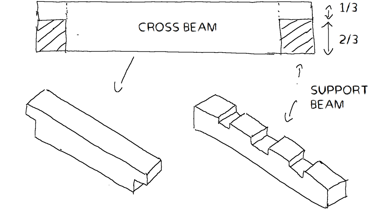
Once these beams are in position, we put on top the cross beams in order to mark the position of the cross lap joints. For this joint we removed ⅓ of the material of the support beam, so as not to weaken the cross section (picture 4). For safety, we also added in the middle a bolt on the support beam, since it is the point where inflection reaches its peak.
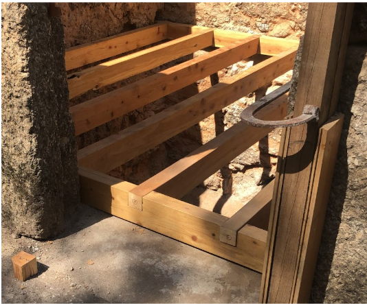
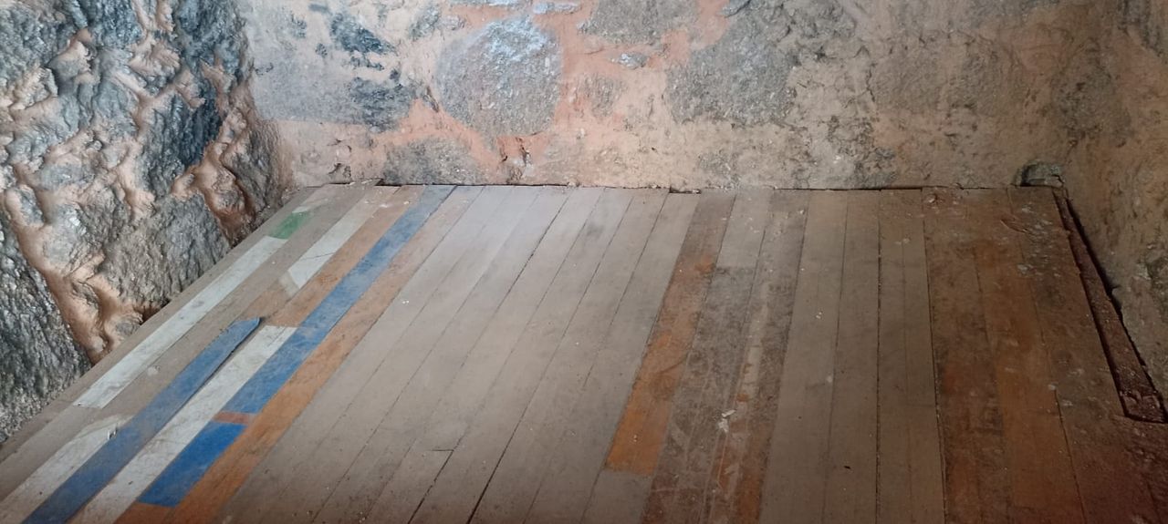
Last but not the least, we installed temporary floor boards (picture 56, since they will get damaged during the rest of the renovation.
12
window support
Published 1y. Edited 1yPublished about 1 year ago. Last edit about 1 year ago
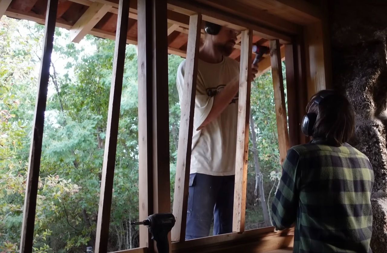
As described in Point 6, the east side of the ruin was removed due to instability and to allow natural sunlight to enter. This leaves the north and south wall freestanding on one side, thus to increase the stability of the walls, support the installation of the windows and bare part of the load of the roof, a reticular structure was designed (I called it throughout the videos window support). We prepared a flat and level surface with mortar mix and stones on the horizontal part of the wall. To facilitate this process, we installed two planks on both sides to act as a guide and reference level (update 134# 12:06).
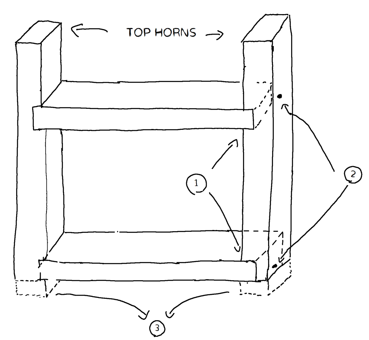
The windows support was built in the following way (picture 2):
First we prepared the beams by flattening them out with a planer and squaring them out with a circular saw. This will facilitate in later stages the installation of the window frame.
1) We cut notches in the vertical beams, this has to be done at the same time on both elements to ensure squareness and a proper fit. You can see this in update #134 around 14:27
2) Screws are put in place to secure the horizontal and vertical beams together
3) The lower horns don’t hold a purpose any more, thus there are sawn away
The top horns will be processed in a later stage to bare part of the load of the roof. Once the window support was built, we measured the diagonals and fixed the structure with wooden scrap once the diagonals were equal, this ensured a 90° on each corner. It also provides stability until the frame is installed (picture 3).
We then tried to fit it in the opening, in some points it was touching the wall, so we slowly chiselled the wall until it fitted properly. Next we bolted the vertical beams (top and bottom part) to the stones that were big enough and not brittle. To ensure the verticality of the frame, we clamped it to the wall to make sure it wouldn't move during the process. In the update we removed and sanded it, this was a bad decision since it got scratched up during the construction of the roof, we had to re-sand it and paint it at the end, so don’t take this as an example!


13
Roof part 1
Published 1y. Edited 1yPublished about 1 year ago. Last edit about 1 year ago
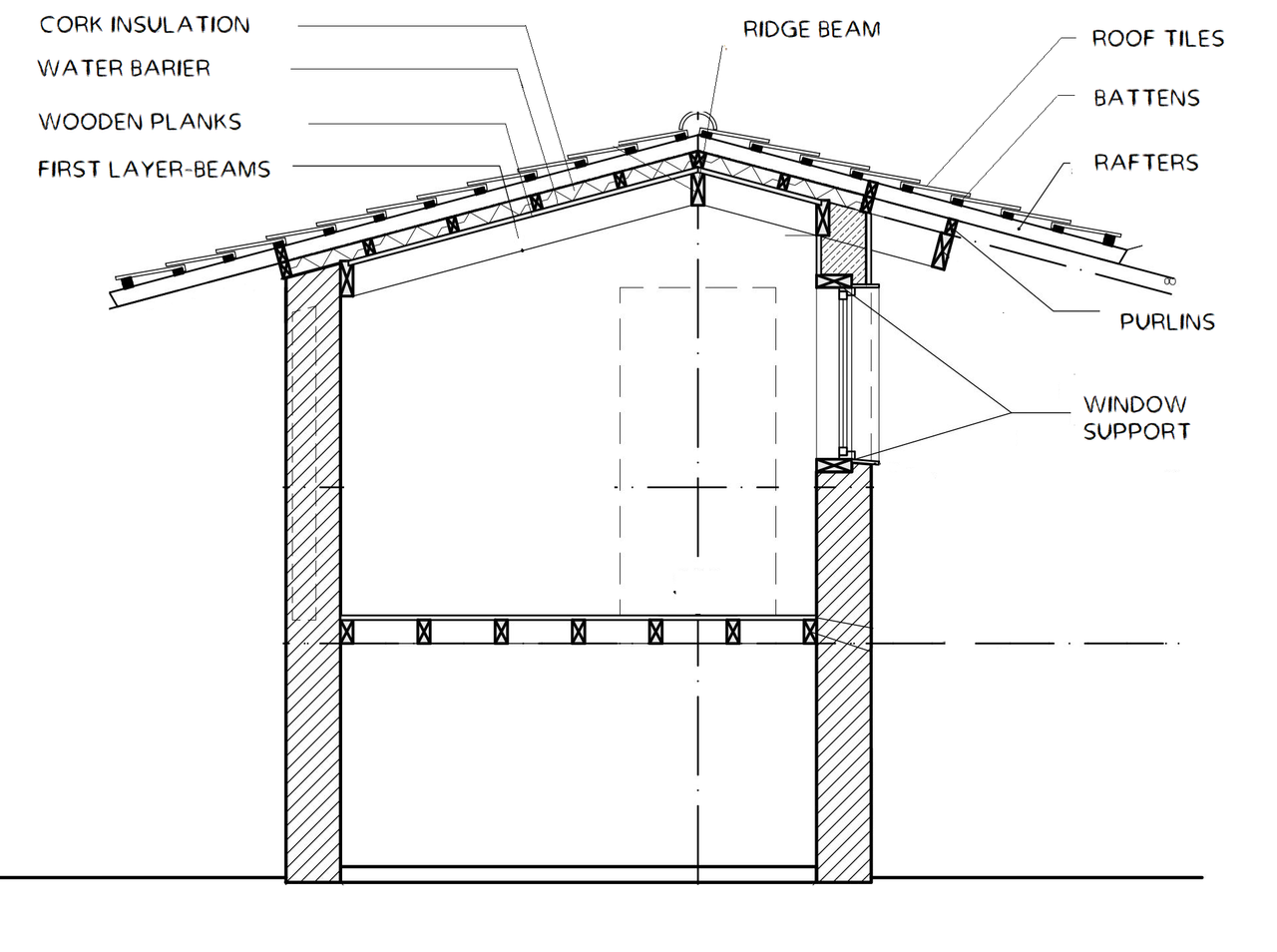
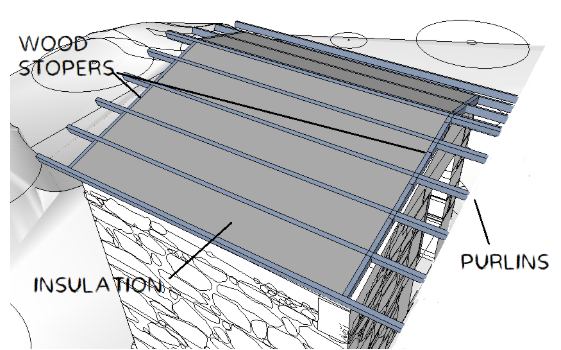
The roof is structured as follows in picture 1, with a more detailed sketch of the first layer in picture 2 (also the most challenging).
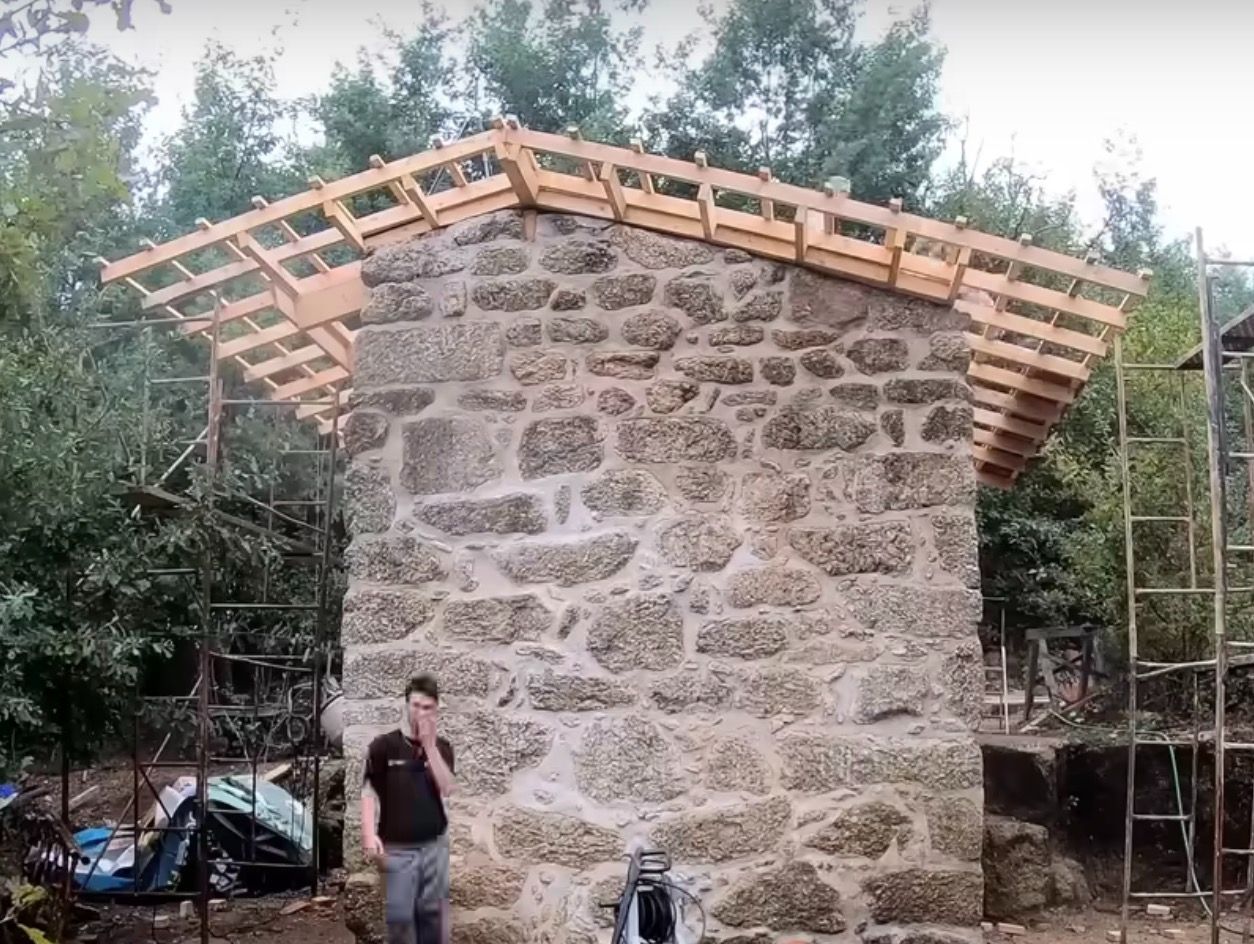
The beams of the first layer rest on the wall, transfering the majority of the weight of the roof, while on the east side they are connected to the window support with an angled T half-lap joint (in the update, I called it always lap joint)
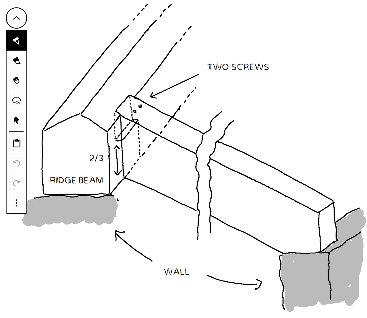
We started by making flat and level the surface where the ridge beam will lie. As done with the floor, we started from one side, which became the reference point for the other side (17:51). On the ridge beam we carved out some notches in order to connect the beams that shoot down, and made the top with a triangular shape, since the wooden planks join at the top.
Next, we installed the wooden planks on the roof, this is quite a straightforward process. We started from the top and went down towards the bottom.
Next we installed the purlins, we used a test piece to have them equally spaced. We checked each one so that if a beam has a bow shape, it has to be put with the concave side facing the sky, since the weight of the roof with time will bring it down. In between the purlins, we put a 10 [cm] insulation layer of cork, and at the ends wood stoppers (I don’t know how there are called) to protect the insulation from the elements, animals and insects.
Next, we put a membrane layer. It has a double function, one to prevent water from entering the structure if the roof gets damaged, the other to let humidity escape from the lower layer. It’s important during installation to:
Put the right side up, it doesn’t work in both directions! Usually the side that faces towards the sky has a grid drawn, useful to have a reference when cutting the sheet
The installation starts from the bottom to the top with staples, and the sheets require an overlap of 10-15 [cm] to avoid water seeping in between.
The staples have to be put under the overlap and under the rafters.
Then we installed the rafters, as before we:
- checked the bow
- used a test piece to have them equally spaced
- put a wooden stopper
The rafters should be cut with some margin, since we want them to be all aligned at the eves of the roof. After installing them, we used a chalk line to mark the final cut, taking into account the positions of the battens.
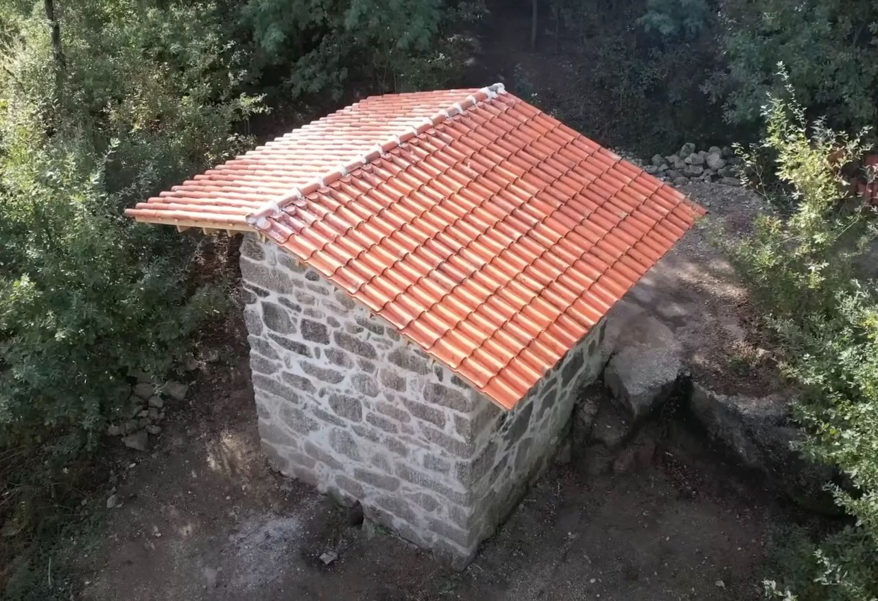
The final step was placing the battens and roof tiles. We reused 30 year old tiles, so we did some selection.
The battens had different thicknesses, so we couldn’t use a test piece to space them equally. We used a chalk line to mark where the top edge of each batten should go.
Rooftiles vary in size (big tolerances). Manufacturers usually specify a distance between the battens. Of course, we didn’t have this information. Instead, we measured the overlap zone and chose a number in the middle, to allow for the size difference of the tiles.
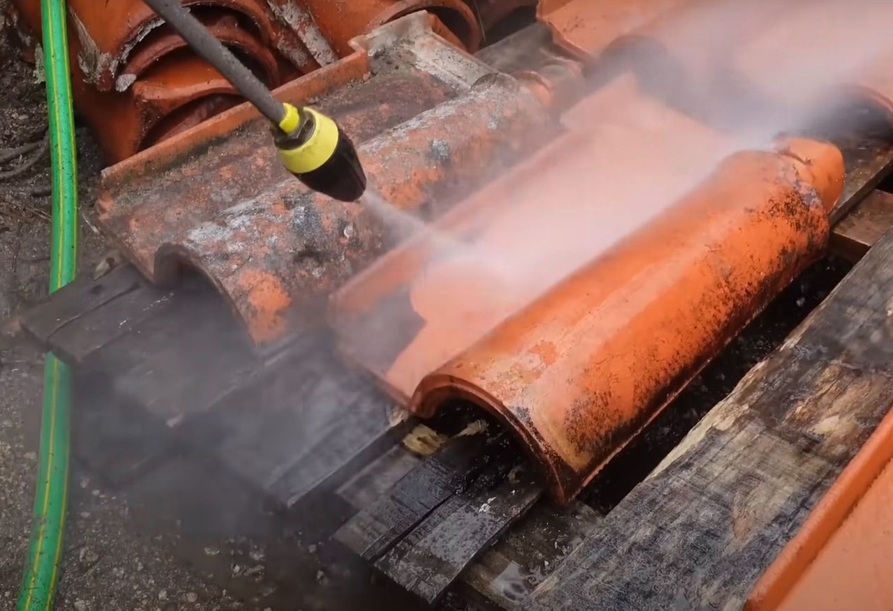
We cleaned the moss off the tiles using a pressure washer so water doesn’t get stuck on the tiles.


14
Windows
Published 1yPublished about 1 year ago
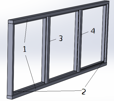
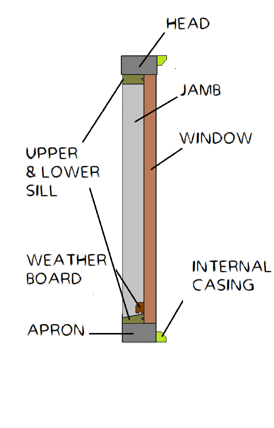
As we previously explained, the windows support is a pre-frame for the windows, this is a good surface to work on since it is flat and square. Given the limited tools available, we designed a very simple frame and ordered the pieces from a local carpenter. In order to accurately install the windows, the sill and the weather board where made a little bit longer and cut to size during the installation.
The frame was mounted in the following way:
1. We screwed the Apron and Head to the window support with screws, carefully putting them where the sills will go so not to be visible
2. We screwed the two lateral jambs, putting them where the groove for the rubber seal will go (this is a classic trick!
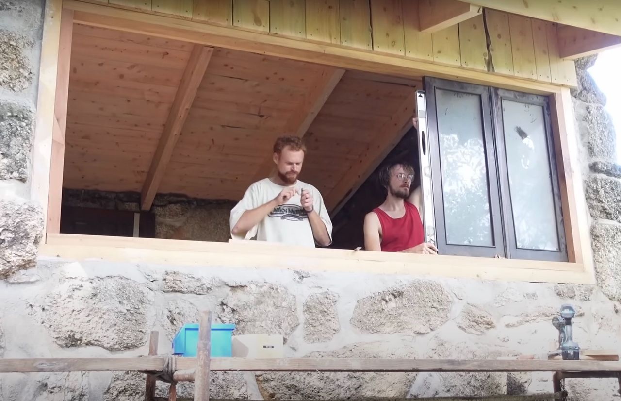
3. We placed a pair of windows onto the frame to mark the position of the jamb (3), and we repeated the same process for (4) (update #137 29:16). This is also important to verify that all the windows fit properly. Then we cut the respective Sills for each pair of windows, since installing them at the same time ensures that the jambs between the windows are perfectly vertical. The Sills are glued directly to the frame with polyurethane glue, we used some sticks to press them since it isn’t possible to use clamps (29:37)
We then installed the hinges; once the windows were in position, we marked the position of the weather board for the windows, since the windows were simple and were lacking them. Last but not the least, we sanded everything and finished with two layers of varnish.
15
Door to first floor
Published 1yPublished about 1 year ago
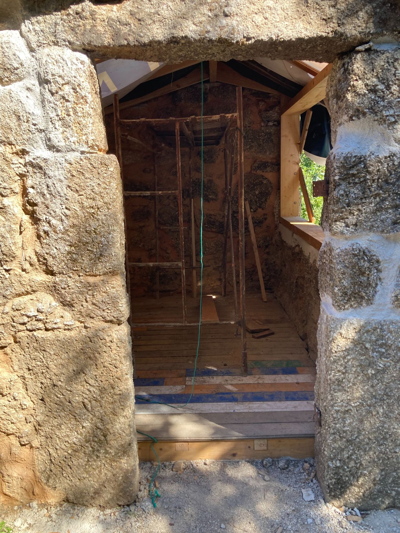
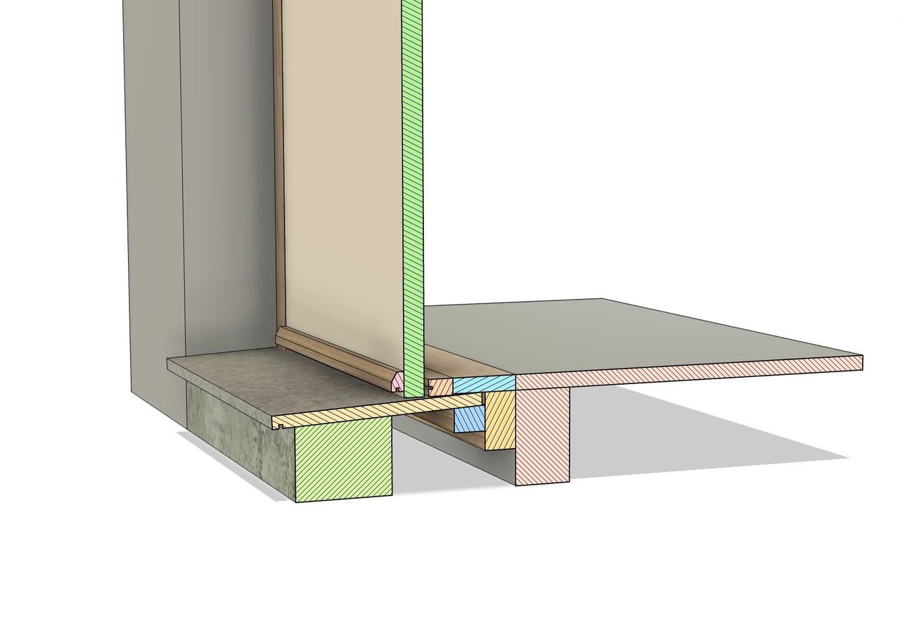
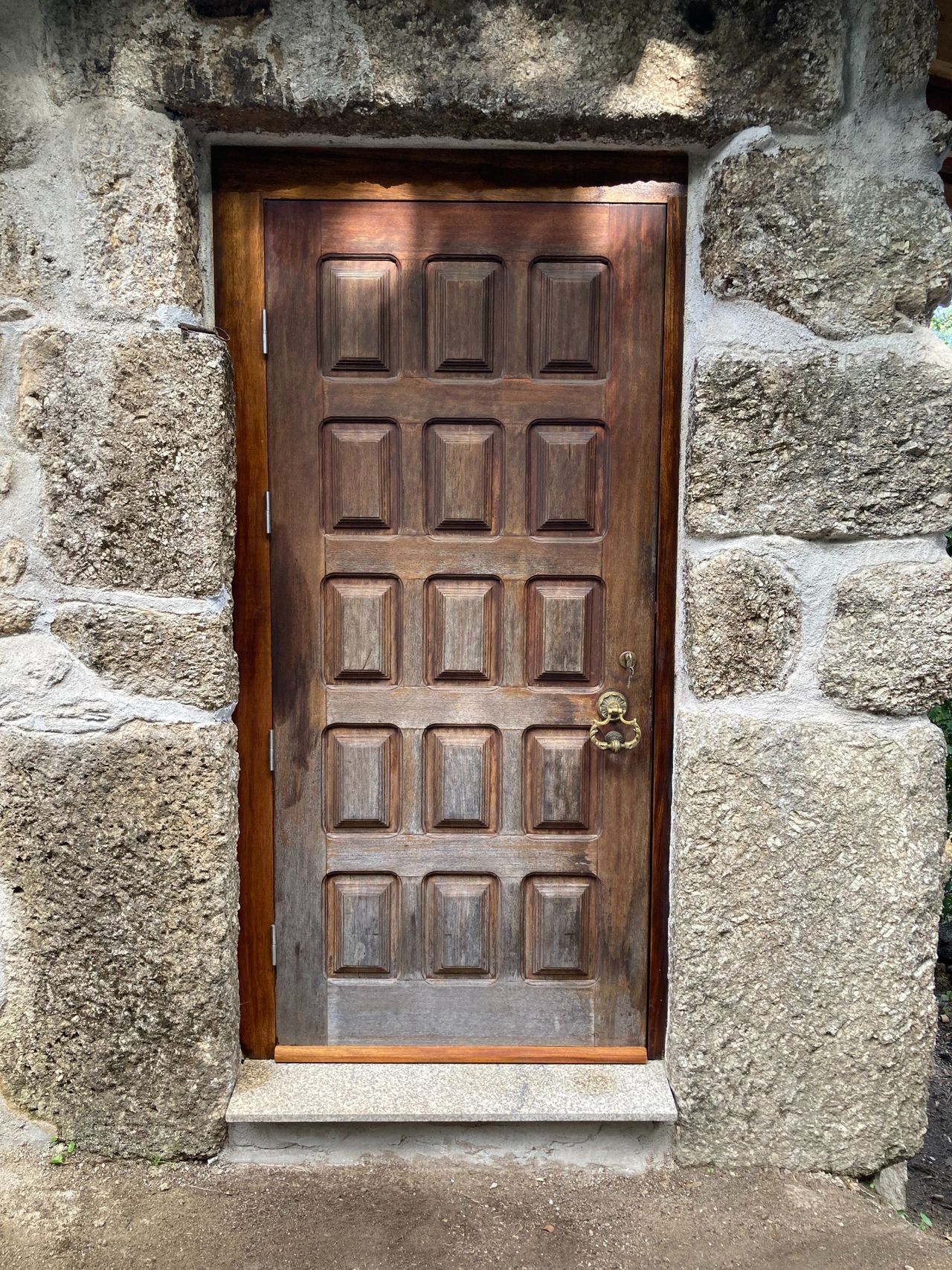
We reused an old door and made a custom frame to fit the door and the ruin.
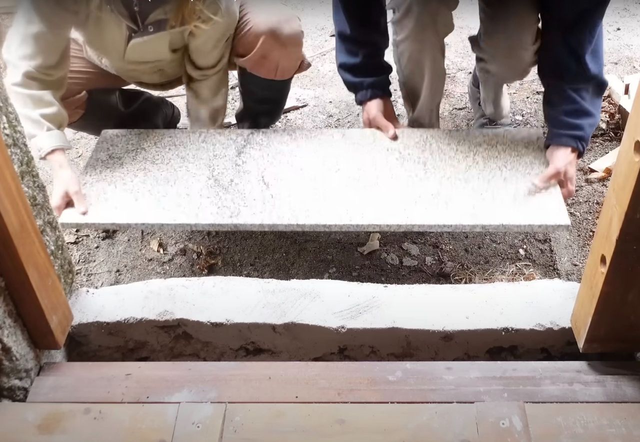
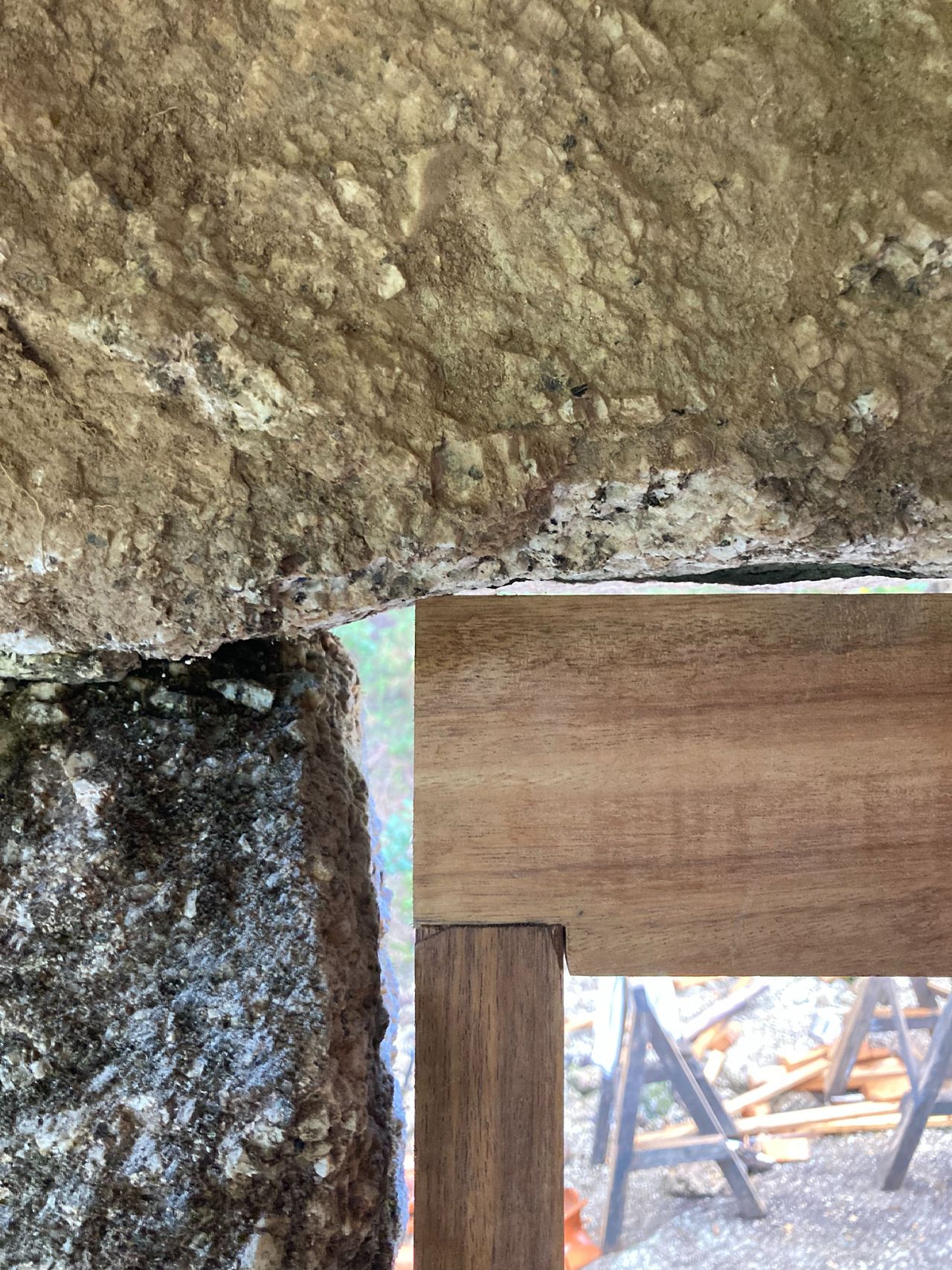
We took measurements from the ruin opening as best we could and made a 3d model to design the frame and doorstep, deciding to place a rubber weather strip all around for better insulation. A local carpenter prepared most of the wooden pieces, so we just had to cut them to size and fit everything. For the threshold we had a piece of granite with a drip groove made. We like to use granite because it is widely available in Portugal. The granite slab rests on a piece of wood with a 3 degree angle (for rainwater) and we made a lime plateau filled with rocks to further support the slab.
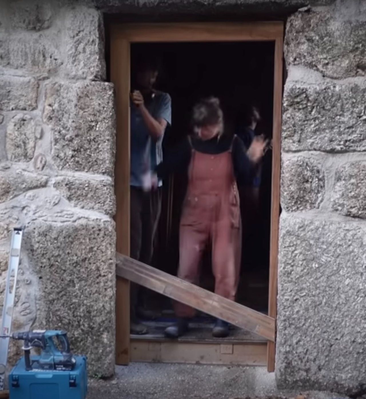
Expansion bolts were used to fix the door frame to the wall.
The granite walls needed to be chiseled to fit the door frame as tightly as possible. Still, there were gaps between the frame and the wall all around. We filled them all with lime.
16
Roof part 2 (outside)
Published 1yPublished about 1 year ago
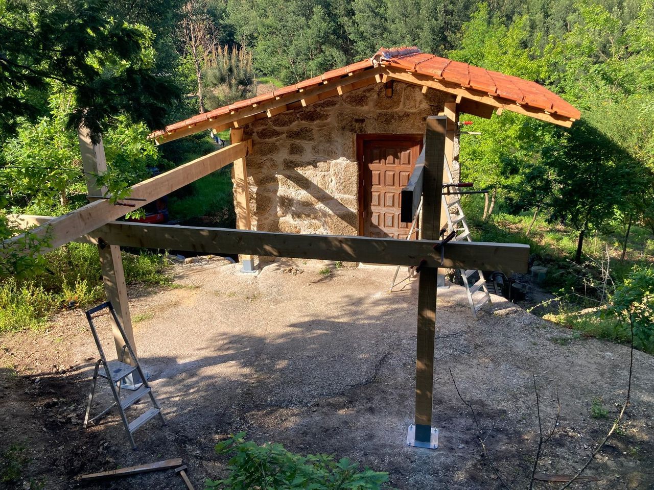
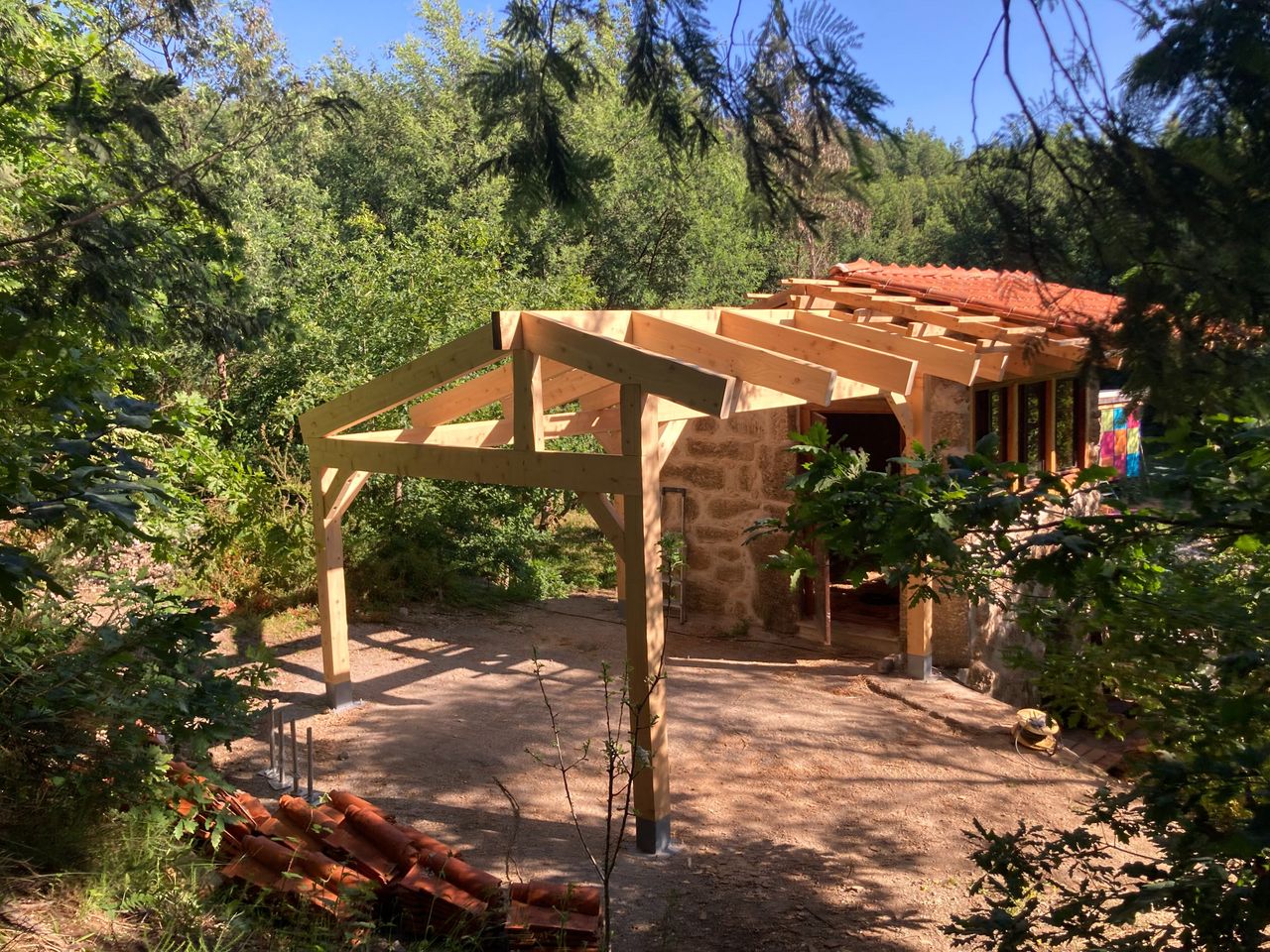
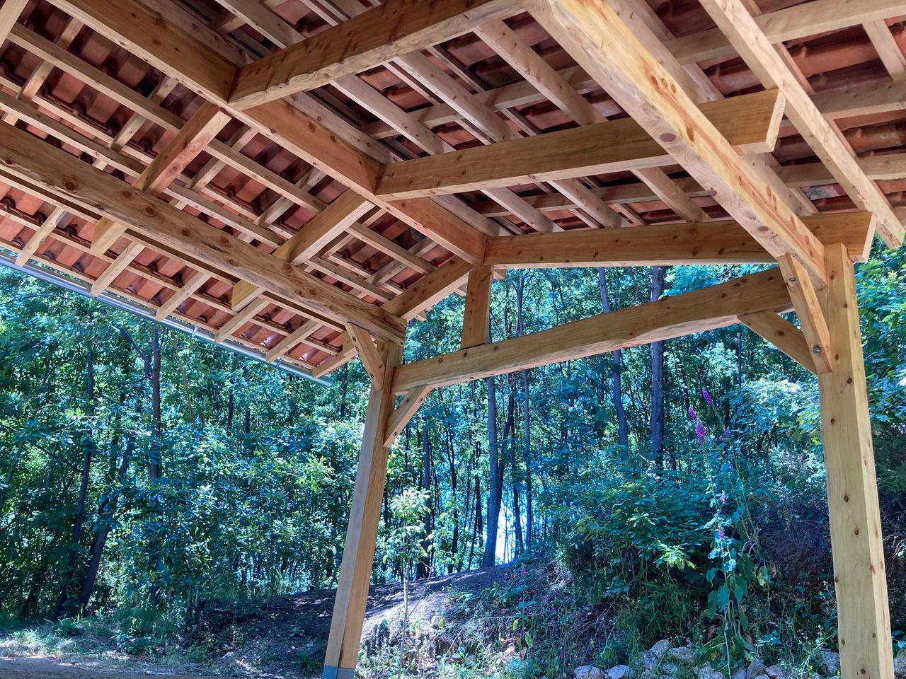
The outside part of the roof was designed with the intention to look like a natural extension from the building. It has a strong structure of beams that supports the (under)purlins, rafters, battens and rooftiles. We made the outside roof almost entirely standalone, because the wall of the ruin is structurally not strong enough to hold the roof by bolting into the face of the wall. The inside and outside roofs are only connected by the ridge beams and the upper wooden layers.
Securing the structure to the ground was a challenge. The structure sits on a big granite boulder. We didn’t want to use any chemicals or cement so we made steel post bases, which we secured to the granite boulder with expansion bolts. To do this, we did a lot of measuring with strings and plumb lines and then a lot of chiseling of the boulder, to make the ground underneath the post bases flat and level.
We did a dry fit of all the posts and first horizontal support beams. This made it possible to mark the notches. Then we made the notches and assembled the beams. We left the beams slightly longer so we could cut them at the right length exactly after assembling everything.
Next, we did a dry fit, notching and assembly of the ridge beam, It is on one side supported by a king post and on the other by the inside ridge beam. On top, main rafters finish the base structure. This and the rest of the roof build was mostly the same as was done earlier, see ‘Roof part 1’ for more information.
Based on feedback we got, we decided not to use a pressure washer to clean the rooftiles. Some people argue that this could make the tiles more fragile. So we only brushed off some excess moss and then placed the tiles on the roof. Over time, we will see if the pressure washed tiles will break sooner than our non-pressure washed tiles.
Challenges:
We encountered a lot of wood rot in our beams, especially in the posts. We took out all the rotten parts because they can hold moisture in and creature problems in the future. We used chisels, scraper tools and sanding paper to create a smooth finish.
We also found a lot of bug holes in the wood that was stored over the winter, even though it is red cedar, which is supposed to be naturally bug repellent. We used harsh chemicals to kill the bugs inside, which we didn’t like. We would love to hear about alternatives to keep our wood bug free!


17
Top floor insulation
Published 9mo. Edited 9moPublished 9 months ago. Last edit 9 months ago
We used a reclaimed basketball floor for the upper and the lower sides of the top floor.
In between we laid down home made insulation blocks made of straw and clay using the LSC technic (Light Straw Clay). Our main challenge was the drying time of the blocks. Because of the low temperatures and the heavy rains, we had some mold issues. We decided to open all the blocks to speed up the drying time. Finally the blocks are fullly dry now thanks to the hot summer days we had. We’ll assess the technic after the winter.
The whole process is explained in this research module:
https://community.projectkamp.com/research/can-we-make-our-own-insulation
18
Plastering top room walls with earthen plasters
Published 9mo. Edited 3moPublished 9 months ago. Last edit 4 months ago
The top floor done, we were able to work on the stone walls of the room. We decided to cover them with clay to flatten them and give them more insulating properties.
The clay mixed with sand and fibers such as oat straw is a perfect material to do so. Easy to prepare and apply onto the walls it was the best option for us. A Lime/sand/hemp mortar could have been great too, but it takes more time to dry (7 days between two coats) and is applied with thin layers of 3 centimeters.
Earthen plasters upsides are:
- Thermal mass
- Humidity regulation, the walls will store the excess of humidity
- Easy maintenance
- the warm feeling
- can be covered with natural paints
Earthen plasters downsides are:
- the drying times
- the fragility (they have to be maintained)
- they can be easily soiled
The whole process is explained in this research module:
https://community.projectkamp.com/research/can-we-plaster-with-clay-on-granite-walls
19
The bottom room: finishing the walls
Published 9moPublished 9 months ago
We decided to plaster the stone walls with a lime mortar as we did for the outside. The idea was not to cover all the stones and the walls flat. We wanted to see the material and have a finish close to the one outside. The result is nice and cosy.
A earthen plaster would have been a bad idea since we have humidity issues in this room. The clay softens when soaked and retains the water as a sponge unlike the lime which will remain stable and hard and will not absorb too much water.
The mortar recipe was the same as usual: 2,5 part lime for 1 part sand
20
The bottom room: challenges (height, humidity)
Published 9moPublished 9 months ago
We had two main Challenges in this room:
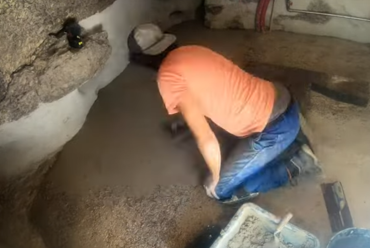
The first one is the humidity. During winter, the “boulder” wall and the one next to it get wet because of the heavy rains. The floor is wet too as it belongs to the same granit boulder. The challenge was to find a way to keep the floor dry while evacuating the humidity from the room with a proper air flow.
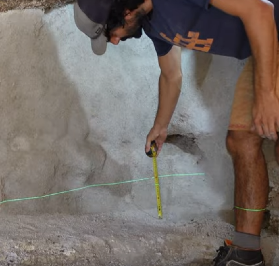
The second challenge is the height. This room has a sloping floor and a really low ceiling. The floor has been dug in the previous season but it’s a long and laborious process. The challenge was to level the floor while keeping a livable space.
21
The “ventilated hedgehog”: a solution to dry the floor
Published 9moPublished 9 months ago
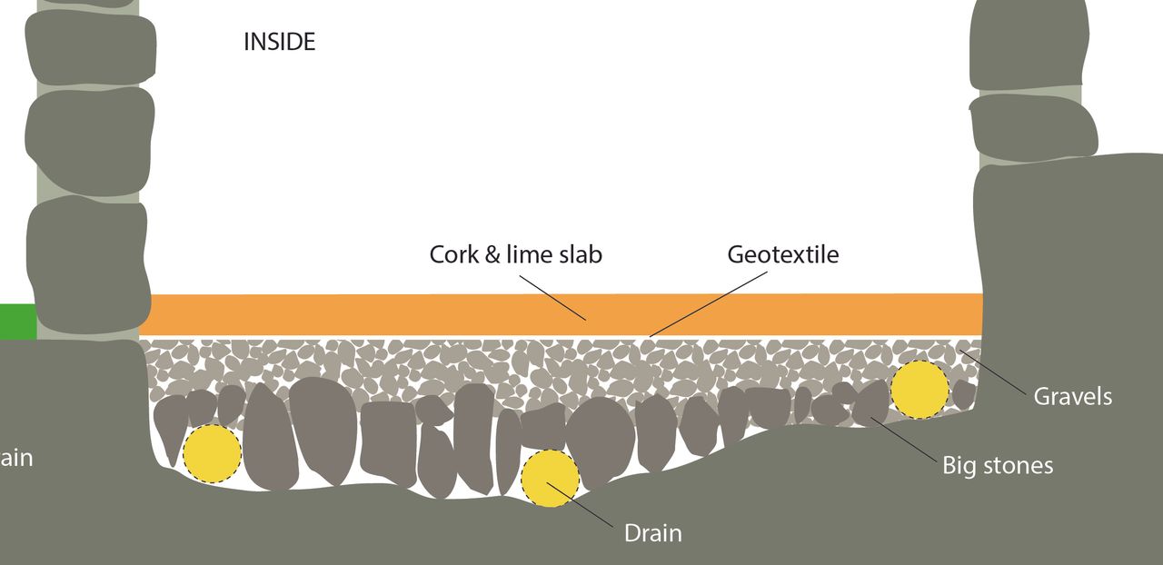
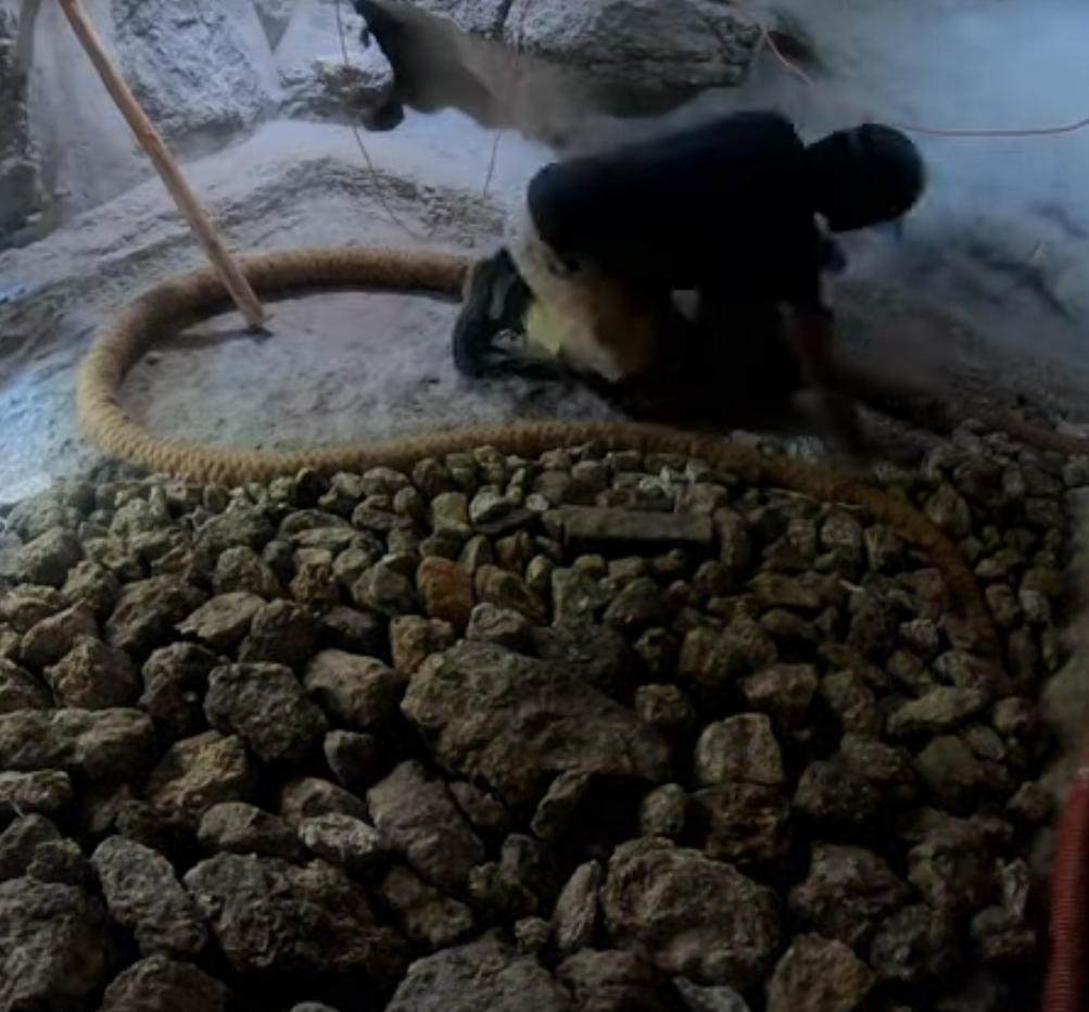
The ventilated hedgehog works like this:
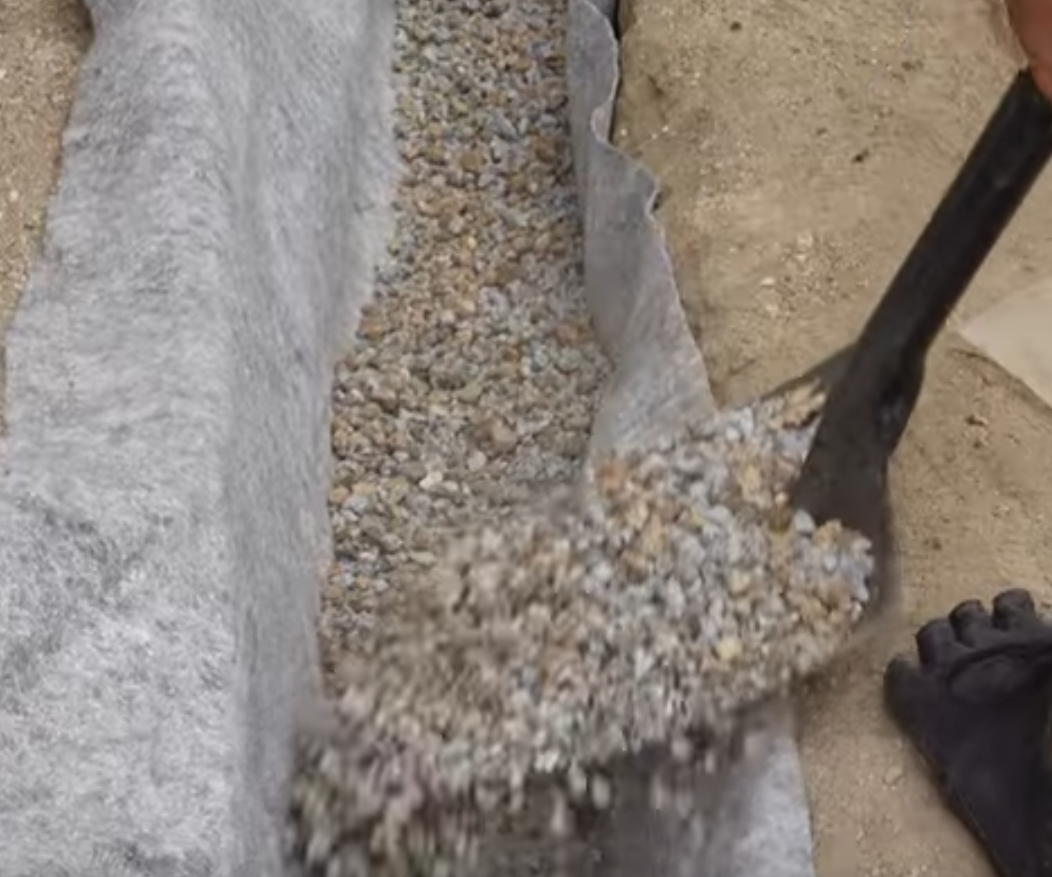
A first layer of big stones (100-200 mm is laid down on the floor. These stones reduce the contact with the ground and allow the air to flow in between the stones. To make so the stones have to be sit on the edge.
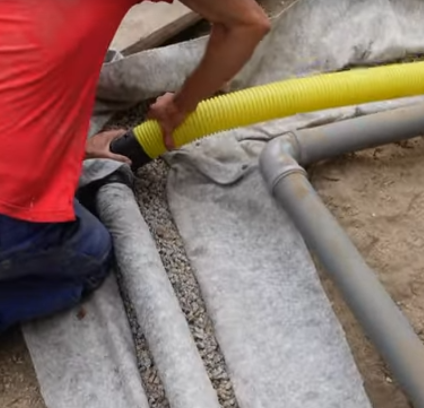
A pipe (drainage) brings fresh air from the outside into the stone layer thanks to the little holes which are drilled all around it.
This airflow evacuate the humidity from the floor towards the outside of the room. The pipe has to snake inside the stones layer and be as close as possible from the walls.
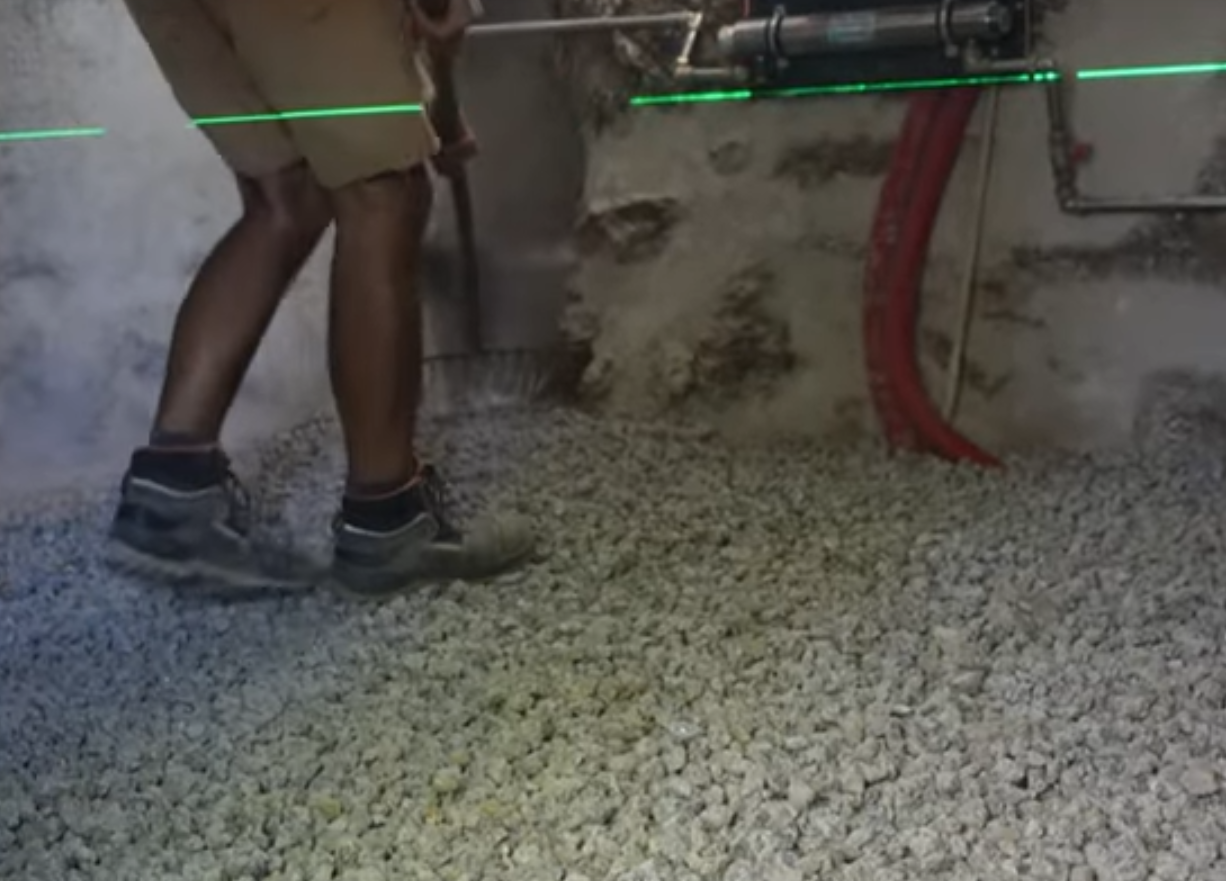
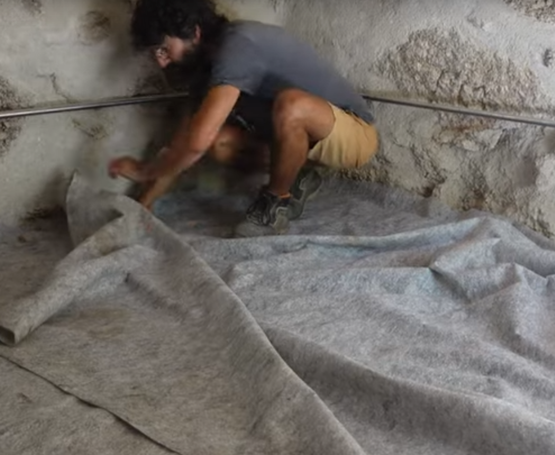
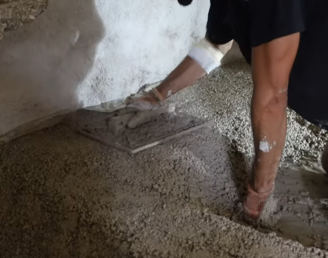
A second layer of gravels (20-40 mm) is poured to level the floor and rammed. A fabric or geotextile covers the gravels layer and finally a slab made of cork and lime is poured on top of it. The slab has to be 150 mm thick mimimum. In our case it was impossible to have this thickness so we shrinked it to 12 mm.
This slab is water proof thanks to the cork and will prevent capillary rises.
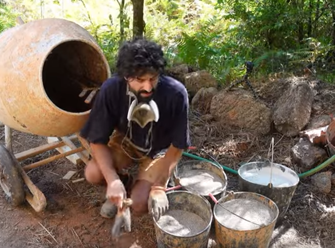
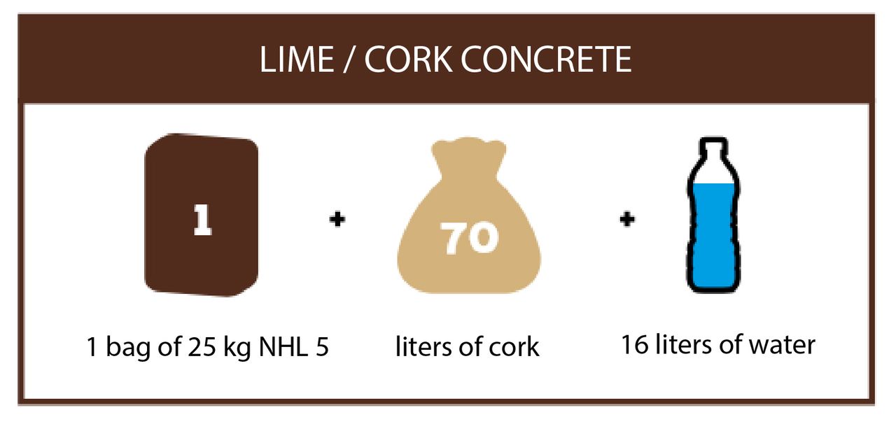
We used this ratio for the lime and cork concrete: 1 bag of 25 kg of NHL 5 + 70 liters of cork (9-15 mm granulates) + 16 liters of water
At the really end of the process I decided to pour a final layer of lime mortar (2,5 thin sand + 1 lime 3.5) to smooth and protect the cork slab.I could have used NHL 5 for this but we were running out of it...
22
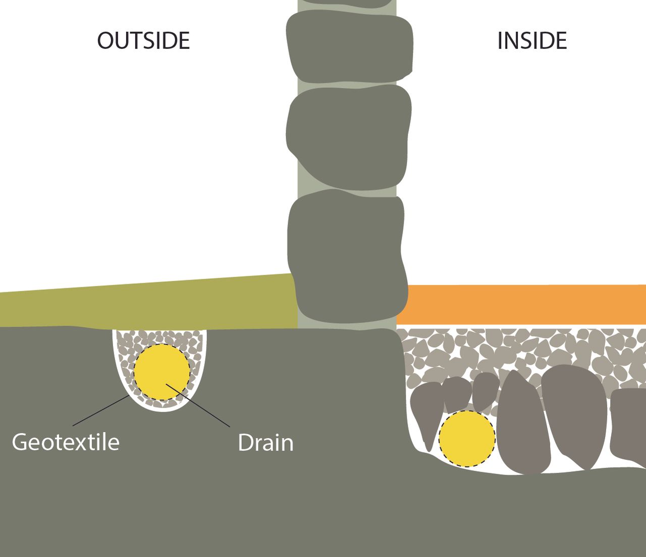
Setting up a french drain outside
Published 9moPublished 9 months ago
We decided to set up a french drain to channel the rain water from the bottom of the walls to a remote place.
The soil underneath the walls is super hard (granite) and prevent the water from infiltrating the ground. The water is stuck on the surface and get into the walls: we call this phenomenon capillary rise.
We first dug a trench, had some gravel, and covered it with a geotextile. Then we had the drain (wraped into a fabric) and covered the it with gravel again. We finally put the dirt back and covered everything making sure we had a slight slope at the bottom of the wall to guide the water to the drain.
%20--%3e%3csvg%20version='1.1'%20id='Layer_1'%20xmlns='http://www.w3.org/2000/svg'%20xmlns:xlink='http://www.w3.org/1999/xlink'%20x='0px'%20y='0px'%20viewBox='0%200%2064%2063'%20style='enable-background:new%200%200%2064%2063;'%20xml:space='preserve'%3e%3cstyle%20type='text/css'%3e%20.st0{fill:%2320B7EB;}%20.st1{fill:%23E9475A;}%20.st2{fill:%23FECE4E;}%20%3c/style%3e%3cdesc%3eCreated%20with%20Sketch.%3c/desc%3e%3cg%20id='Page-1'%3e%3cg%20id='OA-Logo-Black-Background'%3e%3cpath%20id='Shape'%20class='st0'%20d='M14.1,30.1c-1.5-0.8-8.6-3.8-14.1-7.8c1.8-3.4,3.1-5.6,5-9.1c2.7,1.1,1.9,0.5,4.6,1.7%20c0.8,0.4,10.1,4.5,13.8,6.2c2.4,1.1,4.7,2.2,7,3.3L43,30.5l8.1,3.9c4,2,7.2,3.5,11.3,5.5c0.5,0.3-3.7,9.4-3.7,9.4%20c-1.7-0.6-3.9-1.8-5.5-2.5c-4.7-2.1-9-3.9-13.7-6c-4-1.8-6.7-2.9-10.8-4.5C25,34.9,17.1,31.6,14.1,30.1z'/%3e%3cpath%20id='Shape_1_'%20class='st1'%20d='M12.1,54.9c-0.8,0.6-1.6,1.2-2.5,1.6c-0.4-0.5-0.9-1-1.3-1.5c-0.3-1.2-2.3-4.9-2.7-6.2%20c-0.1-0.4-0.7-2.2-0.8-2.6c0,0,5-3.4,8.2-5.9c3.2-2.6,6.2-5,9.3-7.5c1.4-1.1,3.9-2.5,5.3-3.5c2.5-1.7,13-9.1,15.6-10.5%20c5.4-3.3,11.1-6.3,16.8-9c1.7,3.5,1.8,3,3.8,6.9c0,0-17.8,13.5-22.7,17.1c-3.8,2.8-7.5,5.7-11.3,8.5c-1.7,1.3-3.5,2.4-5.2,3.7'/%3e%3cpath%20id='Shape_2_'%20class='st2'%20d='M20.8,2.9l-0.2-0.8C25,0,31.2-0.3,31.4,0.2c0.4,1.1,0.9,2.2,1.2,3.4c1.4,4.4,2.7,8.7,4,13.1%20c0.4,1.4,2.8,10,2.9,10.5c0.5,2.8,1.2,5.6,1.6,8.4c0.8,4.7,1.4,8.6,2.3,13.3c0.6,3.1,1.3,6.3,2.3,11.3c0,0-5.8,1.4-7.5,1.8%20c-0.8,0.2-1.5,0.4-2.4,0.6c-0.3-1.1-0.2-1.2-0.5-2.1c-0.9-3.7-1.8-7.3-2.6-11c-1.5-6.4-3-12.9-4.4-19.3%20c-1.2-5.4-2.6-10.7-4.4-15.9c-1-3.1-1.8-6.3-2.7-9.5C21.1,3.8,21,3.8,20.8,2.9z'/%3e%3c/g%3e%3c/g%3e%3c/svg%3e)